Analysis of Air Supply Air Flow Rate Decrease by Accelerated Dust Load Experiments on Heat-Recovery Ventilator Air Filter
ⓒ 2022. KIEAE all rights reserved.
Abstract
Recently, owing to the high concentration of fine dust, air filters have become essential in heat-recovery ventilators. In Korea, air filter performance is evaluated by the standard, “KS B 6141 Air Filter Units for Ventilation.” However, filter lifetime has not been examined. In this study, an accelerated test method for air filters was developed. In addition, the change in the supply air flow rate was analyzed under filter conditions.
The filter accelerated test conditions were identified, and the annual average concentration of fine dust in the atmosphere was determined. A vertical wind tunnel was built to evaluate the air filter lifetime. The ISO A2 dust was dosed to an air filter. In addition, the supply air flow rates were measured for the three products that the accelerated air filter used.
Under the lab test conditions, the supply air flow rate changed with the filter usage time and the air resistance. In the experiments, only ISO A2 dust was used. Subsequently, the effects of various particles were tested on the development of the acceleration test method for filters.
Keywords:
Ventilation System, Air Filter, Accelerated Evaluation, Supply Air Flow Rate, Test키워드:
환기장치, 에어필터, 가속화 평가, 급기풍량, 시험1. Introduction
1.1. Background and purpose of research
Modern people spend 22h per day indoors[1]. The demand for managing clean air conditions in indoor living spaces is also significantly increasing. Fine dust is one of the air pollutants that is produced both inside and outside spaces. Fine dust has been classified as a group 1 carcinogen by the International Agency for Research on Cancer[2]. In addition, the Organization for Economic Co-operation and Development published a report on the economic analysis of Korea regarding air pollution, such as ultrafine dust. The important issue is that health costs will grow fivefold from $60 billion in 2015 to $280–$290 billion in 2060 owing to a decline in the gross domestic product as well as increase in number of diseases and early mortality[2]. To deal with the problem of external high-concentration fine dust, an international joint study was conducted. The joint research by domestic researchers and the National Aeronautics and Space Administration revealed a high-concentration fine dust in Korea, comprising 48% foreign influences such as China and 52% domestic emissions[2]. By season, it was discovered that the fine dust produced domestically during summer was considerably influenced by atmospheric congestion, whereas that in winter and spring was significantly influenced by foreign countries under the influence of northwesterly and westerly winds.
Thus, the fine dust introduced from the outside and the that generated indoors according to health and environmental changes cause health deterioration and economic losses. The importance of air cleaning technologies for boosting indoor air quality is once again being acknowledged.
The Ministry of Land, Infrastructure, and Transport strengthened the performance requirements for air filters for ventilation systems installed in buildings and mandated the installation of ventilation systems even in apartment buildings with 30 or more households to manage indoor air quality[3]. The leak rate evaluation method of the air that does not pass through an installed air filter and the filter life notification function, among other requirements, are specified in the KS B 6879:2020[4] heat-recovery ventilation system standard, only from the perspective of energy efficiency. The technical standard for supply air flow rate is one of them, and it must be constantly supplied to ensure 70% or higher rated air flow rate at the ultimate ventilation resistance of the air filter unit. Specifically, when a heat-recovery ventilation system is used, the air supply fan continuously modifies the ventilation needed (70% minimum rated air flow rate) to maintain the supply air flow rate according to the cumulative drop in the air filter dust (increase in filter ventilation resistance).
A KS B 6141:2020[5] air filter unit standard for ventilation can be used to evaluate the unit performance of an air filter in its initial state by measuring its particle collection rate, ventilation resistance, and dust collecting quantity. However, an experimental numerical study on performance changes has limitations because collection targets and dust loads differ with the change in the dust collection performance caused by long-term use of an air filter. Research results on filter performance change according to actual use in Korea and are also limited. Furthermore, research results on system efficiency, such as changes in the supply air flow rate and the energy efficiency when an air filter is installed in a heat-recovery type ventilation system, have decreases since the introduction of this system. Moreover, no academic or experimental data exist.
Therefore, this study develops an accelerated load dust test method for an air filter installed in a heat-recovery ventilator to determine the change in its air supply volume according to the change in its lifespan. Moreover. for air filters of three manufacturers, the differential pressure and life changes in accelerated dust load tests were confirmed. Furthermore, the alteration in the supply air flow rate of the heat-recovery-type ventilation device due to a change in the test dust supply amount was examined.
1.2. Research method and scope
In this study, we identified the academic limitations of air filter life evaluation based on long-term use in an actual environments. Moreover, we developed a method to predict filter life in a short time by conducting air filter accelerated dust load experiments in a laboratory. In the experiments, three commercially available products with same specifications were selected and a comparative evaluation were examined.
2. Review of previous research
Several studies have been conducted to evaluate the performance of air filters used in ventilation systems. In addition, various test standards have been established worldwide. Park (2013) introduced international test standards for evaluating the performance of air filters used in general ventilation. Focusing on ASHRAE 52.2 and EN 779[6], the standard developed by Lee and Shin (2017) is for high-efficiency particulate air (HEPA)/ultralow particulate air filter performance evaluation standard. Moreover, the testing procedure for the performance evaluation of high-performance air filters was analyzed based on EN 1822, which is the most influential standard[7].
Based on these test standards, several existing studies have been conducted on heat-recovery ventilators. Moreover, recently, many analysis and evaluation studies on the overall performance, heat exchange efficiency, and energy consumption performance were conducted.
Byeong-yong et al. (2022) confirmed the performance level of a heat-recovery ventilator and the performance change of an installed air filter. The performance distribution and standardization trends of released heat-recovery ventilator products by the air flow rate were examined and evaluated[8]. Kyung-joo et al. (2022) conducted an experimental investigation on the influence of the fan power variation and ultrafine dust removal on the performance of a heat-recovery ventilator filter. As an on-site empirical study on a heat-recovery ventilator installed in an apartment building, the ultrafine dust reduction performance and the degree of increase in power were confirmed[9]. Young-mo et al. (2020) investigated the performance change of a heat-recovery type ventilation system based on the use of various dust-collecting filters. A pre-filter and H11, H12, and H13 grade dust-collecting filters were used in the heat-recovery ventilation system, and its performance was evaluated in terms of the leakage rate, energy coefficient, noise, and cleaning capability[10]. Ye-rim and Min-gi (2021) tested the performance of a filter in an operational heat-recovery ventilator. These studies emphasize the necessity of developing a new performance test standard that can evaluate the removal effectiveness of a filter attached to a mechanical ventilation system in the field was emphasized[11].
In addition, previous research on the analysis of energy consumption performance based on the changes in filter differential pressure were found. Won et al. (2004) performed dynamic simulations to examine the influence of filter clogging on the overall energy consumption. This was because the energy consumption of continuous air conditioners is practically impossible to study owing to filter clogging in the field[12].
3. Accelerated dust load experiments on air filter
3.1. Test method
An accelerated dust load experiment on an air filter increases the test dust supply to it and measures the change in the differential pressure of filters due to the dust accumulated in the air filter in a short period. It also analyzes the life cycle based on the relationship between the amount of injected dust and the differential pressure. In general, the life of a filter is estimated by the amount of test dust supplied and the concentration of the dust to the pressure loss of the final ventilation resistance. However, this is simply a method of determining the final performance efficiency.
In real environments, various forms of dust with varying particle diameter distributions, densities, and shapes pass through an air filter and become attached to it. Consequently, they collect the moisture in the air, reduce the life of the filter, and influence the change in the filter life. Therefore, determining filter lifespan in real applications is difficult.
Furthermore, even in a laboratory, forecasting the lifespan of an air filter is impossible because a technique to evaluate the performance change due to dust collection has not been developed. Therefore, in this study, we established a test method that uses a vertical wind tunnel. instead of a horizontal wind tunnel as recommended by existing domestic and international standards. The method was designed to minimize the effects of air flow stability before and after the filter, problem of dust adhering to the filter and re-dispersion, and gravity settling due to the weight of each particle.
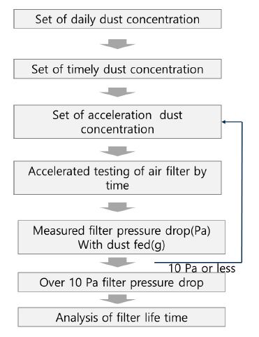
The ANSI/ASHRAE 52.2 10.7 Test Program for Dust-Loading and Particle Size Efficiency was developed to define the accelerated test procedure for air filter life[13]. The pressure drop was determined to be increased by 10Pa. Specifically, the replacement life was determined when the difference pressure before and after the air filter increased by 10Pa owing to the attachment of fine dust in the initial condition of the air filter.
The daily average domestic fine dust concentration and the air particle size distribution were investigated to establish the standard for test dust for the accelerated pressure drop experiments. This was done to study the attachment of suspended dust to the air filter, and the time average concentration was selected. The life of each air filter was estimated after calculating the pressure drop duration depending on the concentration of dust in the accelerated tests. By analyzing the slope of time function (t) versus pressure drop graph of each air filter used in the accelerated experiments, the lifetime of an air was estimated.
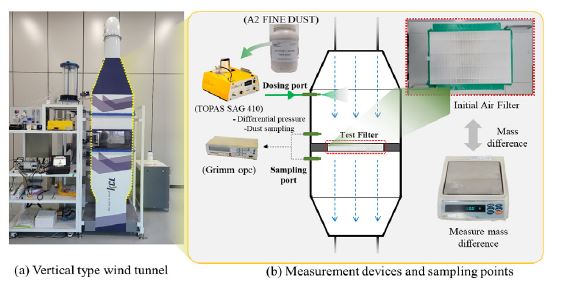
The process of the air filter life accelerated experiment is shown in Fig. 1. Fig. 2. shows the construction images of the vertical wind tunnel built for the air filter life accelerated tests. A TOPAS SAG 410 fine dust generator was developed using experimental equipment to produce fine dust quantitatively. Table 1. lists the equipment specifications and particle types utilized in the experiments.

Schematics of testing device: (a) vertical-type wind tunnel and (b) measurement devices and sampling points
Assuming PM10 in air, dust of size 10μm or smaller was supplied using the A2 dust test dust, as described in ISO 12103-1. The weight change caused by dust attachment to the air filter and the pressure drop before and after the air filter were monitored simultaneously. The weight change of the air filter was measured once an hour using a 0.01g balance. The experiments were qualified for numerous Korea Laboratory Accreditation Scheme (KOLAS) ANSI/ASHRAE 52.2 standard assessment methodologies and conducted by individuals with established experimental competence, reducing human error.
To determine the amount of simulation dust generated in the accelerated experiments, the average annual PM10 concentration suggested in the previous literature[14] was approximately 50 μg/m3. Accordingly, the amount of simulation dust was determined to be approximately 50 μg/m3 per day. For example, if the weight of the air filter was measured 1 h after the start of the experiment and it changed by 200g, a 100-h accelerated experiment was considered completed. The accelerated life cycle of an air filter was measured in four-month increments in these experiments.
3.2. Test result
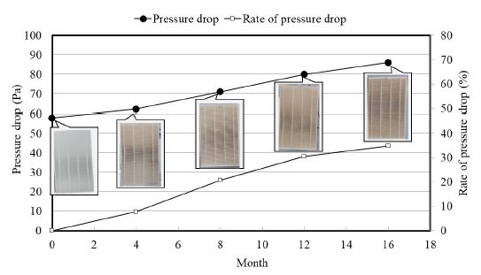
Based on the accelerated tests on the air filter, Table 2. summarizes the results of the pressure difference before and after the filter, differential pressure change rate, and supply quantity of standard particles. The target air filter collected approximately 6mg/m3 of dust per hour in the accelerated experiments. This was estimated from the entering dust corresponding to the fine dust concentration for approximately 1.5 months. The air filter differential pressure increased throughout the accelerated experiments; however, a rapid differential pressure change was not confirmed with 67Pa. An increase of approximately 20% compared to the initial differential pressure was obtained based on a six-month air filter replacement cycle. This replacement cycle is according to the ANSI/ASHRAE 52.2 standard. However, these results were obtained by examining only one type of A2 standard particle. Therefore, developing an accelerated dust test technique for air filters in the future by a complete evaluation of various particles and generation quantities is important.
4. Change in supply air flow rate of heat-recovery ventilation system
4.1. Test Target
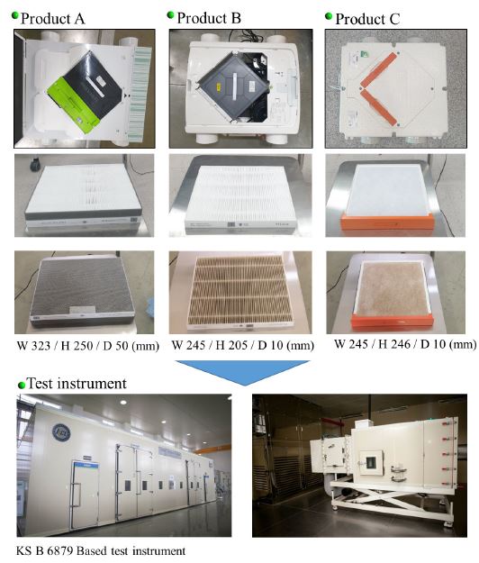
In this study, the changes in the supply air flow rate before and after accelerated tests on the air filters of three heat-recovery ventilators sold in Korea were investigated. All three equipment are KS-certified and important procurement products. Each heat-recovery ventilator is a buried duct type with a plate-type heat exchange mechanism. All three equipment have a rated air flow rate of 150m3/h. One prefilter and a KS B 6141 type-2 grade dry filter are installed on the air supply side air filter.
Photographs of the product to be assessed, initial filter, and filter after the accelerated test are shown in Fig. 4. The air flow rate tests were conducted by measuring the air flow rate by the differential pressure measurement using a multinozzle chamber in accordance with the KS B6879:2020 9.3 air flow rate test methodology. The test equipment fulfilled the KOLAS accreditation criteria of an internationally recognized institution, and the sensor was calibrated annually.
Because the objective product is a duct, it achieves a static pressure outside an aircraft of 100Pa while accounting for the frictional resistance of the air flow rate. For the air flow rate measurements, the air filter of each product was first subjected to accelerated processing using the air filter accelerated dust load method described in Section 3.1. The accelerated conditions were 150%, 200%, 250%, and 350% in phases before and after an ultimate aeration resistance of 250Pa or lower (rate of filter drop 250%) by the KS B 6141 standard. The air flow rate tests were performed again after reinstalling the accelerated filters in the devices of each product group.
A total of four samples of each product were used. After the air filter unit installation, the initial supply air flow rate was measured. The air supply air flow rate was re-measured on installing filter with accumulated and decreased dust.
The air flow rate of each heat-recovery type ventilation system was measured with the supply and exhaust air flow rates, and in this study only the effects of the change in the supply air flow rate were investigated.
4.2. Test result
Table 3. summarizes the results of the air supply air flow rate change tests according to the air filter accelerated tests. The KS B 6141:2020 ventilation air filter unit standard particle collection rate test is defined as the difference in the final pressure that can be used with the specified performance as the final resistance to the air flow of the proposed value. The ventilation resistance at the rated flow rate was 245Pa or lower. In these experiments, each supply air flow rate was measured by adding dust; therefore, the ventilation resistance conditions of the filter placed in each product were 150%, 200%, 250%, and 350%.
Although the filter placed in each product was the same, the size, capacity, and thickness of the filter varied for different products. This was considered to produce a variation in the collecting capacity of the filter. In the case of product A, the air flow rate reduction was 10% when the filter life was 9.9 months. Moreover, the air flow rate reduction was 19% when the filter life was 11.7 months and the filter ventilation resistance was 250Pa. When the filter ventilation resistance of product B approached 250Pa (filter life lifetime of 4 months), the supplied air flow rate significantly reduced. The change in the supply air flow rate was verified to be different for each product, based on the performance of the filter mounted in the product, such as the collecting capacity and the ventilation resistance.
These tests confirmed that the reduction in the supply air flow rate was varied depending on the degree of usage in the accelerated tests of the filters fitted in the heat-recovery type ventilation devices.
Compensation for the supply air flow rate based on filter resistance is required; hence, an acceptable approach for heat-recovery type ventilation systems must be developed. In a simple fan outlet, the compensation control method of the supply air flow rate using a differential pressure sensor or the rotational speed is considered to be limited. It is necessary to recognize the limitations of this study conducted using accelerated dust load experiments with one type of particle and to examine how various particles affect the supply air flow rate by a comprehensive effect. Furthermore, it is proven that filter replacement at an appropriate time is required utilizing a filter lifespan sensor and a compensation control technology for the air supply fan air flow rate.
5. Conclusion
In this study, a method for accelerating the air filter of an apartment house ventilation system was developed, and the air supply reduction was tested by installing accelerated filters. The conclusions are summarized as follows:
(1) Accelerated experiments were conducted over the life of an air filter utilizing data from external fine dust concentration measurements. It used a generation amount of approximately 2.2 μg/m3h (converted amount from external yearly concentration) every hour considering PM10. Even at the six-month interval of the general air filter replacement cycle, the difference in the pressure before and after the air filter did not vary rapidly, and the air filter life was considered intact.
(2) Following the air filter dust acceleration tests under four ventilation resistance change cases for each product, the change in the supply air flow rate was validated by placing an air filter in each ventilation device. The change in the air supply air flow rate varied depending on the number of months the filter was utilized. The results showed that ventilation must be ensured by a suitable compensation management technique for the supply air flow rate based on the change in the filter usage cycle.
In the future, we intend to investigate the effects of other factors on the measured results by evaluating the differential pressure change before and after the air filter based on particle size and particle formation quantity for accelerated tests. We aim to collect fundamental data to develop a model for predicting the life of air filters.
Acknowledgments
This study was supported by the Academic Research Fund of the Kumo Institute of Technology (202000930001).
References
- National Institute of Environmental Research, 2009, A Study on Management of Major Indoor Air Pollutants by House Type in Korea(I) - Indoor Air pollution and Health Effects in Residential Apartment.
-
환경부, “제3차 미세먼지 관리 종합계획”, http://www.me.go.kr/home/web/policy_data/read.do?pagerOffset=0&maxPageItems=10&maxIndexPages=10&searchKey=title&searchValue=%EB%AF%B8%EC%84%B8%EB%A8%BC%EC%A7%80&menuId=10259&orgCd=&condition.deleteYn=N&seq=7399, , 2022.10.24.
Ministry of Environment., “The 3rd comprehensive plan for fine dust manamgement”, http://www.me.go.kr/home/web/policy_data/read.do?pagerOffset=0&maxPageItems=10&maxIndexPages=10&searchKey=title&searchValue=%EB%AF%B8%EC%84%B8%EB%A8%BC%EC%A7%80&menuId=10259&orgCd=&condition.deleteYn=N&seq=7399, , 2022.10.24. -
국토교통부, 건축물의 설비기준에 관한 규칙, 국토교통부 고시 제2015-1108호.
Ministry of Land, Infrastructure and Transport, 2017, Standard of Building Energy Saving, MLIT criteria 2015-1108. - KSA, 2020, KS B 6879:2020 Heat Exchange Ventilatior, Korean Standards Association.
- KSA, 2020, KS B 6311:2020, Air Filter Units for Ventilation, Korean Standards Association.
-
박현설, 일반 환기용 에어필터 성능평가를 위한 국제 시험기준, 공기청정기술, 제26권 제4호, 2013, pp.39-60.
H.S. Park, International test standards for the performance evaluation of air filters for general ventilation, Air Cleaning Technology, 26(4), 2013, pp.39-60. -
이윤규, 신철웅, 고성능 에어필터 성능평가를 위한 시험방법(EN 1822), 건축환경설비, 제11권 제3호, 2017, pp.23-31.
Y.G. Lee, C.H. Shin, Test method for performance evaluation of high performance air filter, Architectural Sustainable Environment and Building Systems, 11(3), 2017, pp.23-31. -
박병용, 조진균, 오병철, 열회수형환기장치의 성능 현황 및 평가방법에 관한 연구, 설비공학논문집, 제34권 제3호, 2022, pp.145-153.
B.Y. Park, J.K. Cho, B.C. Oh, A Study on Performance Status and Test Standard of Heat Recovery Ventilator, Korean Journal of Air-Conditioning and Refrigeration Engineering, 34(3), 2022, pp.145-153. [ https://doi.org/10.6110/KJACR.2022.34.3.145 ]
-
조경주, 조동우, 김태연, 열회수 환기장치의 필터성능에 따른 팬동력 변화 및 초미세먼지 제거효과 실험 연구-열회수 환기장치의 내기순환모드를 중심으로, KIEAE Journal, 제20권 제4호, 2020, pp.77-82.
K.J. Cho, D.W. Cho, T.Y. Kim, Experimental Study on the Fan Power Changes and Ultra-fine Dust Removals depending on Different Filters of Heat Recovery Ventilation Systems - Focused on the Circulation Mode of Heat Recovery Ventilation System, KIEAE Journal, 20(4), 2020, pp.77-82. [ https://doi.org/10.12813/kieae.2020.20.4.077 ]
-
강영모 외 4인, 다양한 집진필터의 적용에 따른 열회수형 환기장치의 성능 변화에 대한 연구, 설비공학논문집, 제32권 제4호, 2020, pp.165-172.
Y.M. Kang et al., A Study on the performance variations of an energy-recovery ventilator using a Pre-filter and HEPA grade filters, Korean Journal of Air-Conditioning and Refrigeration Engineering, 32(4), 2020, pp.165-172. [ https://doi.org/10.6110/KJACR.2020.32.4.165 ]
-
조예림, 성민기, 필터가 장착된 열회수형 환기장치의 미세먼지 제거 성능 실험, 대한건축학회논문집, 제37권 제10호, 2021, pp.149-157.
Y.L. Jo, M.K. Sung, Experimental verification for particle removal efficiency of heat recovery ventilation systems with air filters, Journal of the Architectural Institute of Korea, 37(10), 2021, pp.149-157. -
원근호, 곽노열, 허정호, 공조설비의 필터차압 변화에 따른 에너지 소비성능 평가, 설비공학논문집, 제16권 제12호, 2004, pp.1227-1233.
K.H. Won, R.Y. Kwak, J.H. Huh, Evaluation of energy consumption of HVAC system for air filter pressure difference change in commercial buildings, Korean Journal of Air-Conditioning and Refrigeration Engineering, 16(12), 2004, pp.1227-1233. - ANSI/ASHRAE, 2017, 52.2 Test Program for Dust-Loading and Particle Size Efficiency.
-
여민주, 김용표, 우리나라 미세먼지 농도 추이와 고농도 발생 현황, 한국대기환경학회, 제35권 제2호, 2019, pp.249-264.
M.J. Yeo, Y.P. Kim, Trends of the PM10 concentration and High PM10 concentration cases in Korea, J. Korean Soc. Atmos. Environ, 35(2), 2019, pp.249-264. [ https://doi.org/10.5572/KOSAE.2019.35.2.249 ]


