The Study on Thermal Performance Evaluation of Building Envelope with VIPs
**Dept. of Architectural Engineeging, Kongju National University, Korea
***Green Energy Technology Research Center, Kongju National University, Korea
****Corresponding author, Dept. of Architectural Engineering, Kongju National University, Korea jtkim@kongju.ac.kr
© Copyright Korea Institute of Ecological Architecture and Environment
Abstract
The energy consumption in buildings has continuously increased in some countries and it reaches almost 25% of the total energy use in korea. Therefore there are various efforts to minimize energy consumption in buildings, and the regulations on building envelope insulation have been tightened up gradually. To satisfy the building regulation, the use of vacuum insulation panels(VIPs) is increasing. VIP is a high performance insulation materials, so that it can be thinner than conventional insulation material. When VIP is applied in a building, it may cause thermal bridge, which occurs due to very low thermal conductivity compared to other building materials and the envelope of VIPs.
This study designed the capsulized VIPs using conventional insulation for reduction of the thermal bridge. Then designed VIPs were applied to a wall. The linear thermal transmittance and the effective thermal conductivity were analyzed by HEAT2 simulation program for two dimensional steady-state heat transfer. The result compared with a wall with non-capsulized VIPs.
It analyzed that the wall with capsulized VIPs had lower linear thermal transmittance and reduced the difference of the effective thermal transmittance with one dimensional thermal transmittance compared to that of the wall with non-capsulized VIPs.
Keywords:
Vacuum insulation panel, Lineal thermal transmittance, Effective thermal transmittance(U-value), Thermal bridge, Buildig Envelope키워드:
진공단열패널, 선형열관류율, 유효열관류율, 열교, 건물외피1. Introduction
1.1. Background and Purpose
As the entire world suffers from environmental problems such as abnormal climate change and global warming, international societies have made a variety of efforts to reduce greenhouse gases such as Rio Convention on Climatic Change and Kyoto Protocol. To keep abreast of such efforts, the government has set the target for zero-energy house by 2025 by reinforcing the regulation on energy consumption in construction sector by stage, which takes more than 25% of the total energy consumption.[1]
To reduce the energy consumption in architectural sector, it is necessary to reinforce thermal insulation of building envelope and minimize energy loss from the envelope. Expanded Polystyrene Board (EPS) or glass-wool can be added to existing insulating materials for greater thickness, or high efficiency-insulating materials such as vacuum insulation panels (VIPs) and aerogel, of which thermal conductivity is lower than existing insulating materials can be used to improve the thermal insulation of walls. However, increasing the thickness of existing insulating materials has an accompanying problem: as the thickness increases, the effective area of indoor space decreases.[2] Therefore, VIPs of which thermal conductivity is lower than existing insulating materials is on high demand.
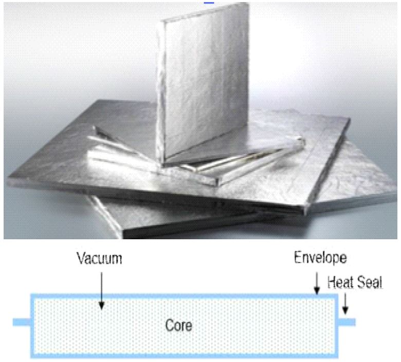
As seen in Figure 1[3], VIPs consists of metal envelope that is composit of core material (e.g. fumed silica and glass-wool), protection layer, and film and heat seal. In addition, getter and desiccant are additionally used to absorb moisture and gas permeating into metal envelope at atmospheric pressure.[2]
Metal envelope can be divided by thickness and lamination type. Because it is made (composited) of metal with high thermal conductivity, it is prone to heat loss mainly in the thermal bridge of VIPs themselves.[4] Furthermore, heat loss takes place at anchor, wood, and plastic on which VIPs are fixed to a wall. Because installation member has relatively higher thermal conductivity than VIPs, heat loses through installation member, which becomes the thermal bridge of VIP wall. Thermal bridge that happens to VIPs varies depending on the material of metal envelope or the type of installation member, which has a great impact on the heat insulation performance of a wall.
The study[5] of VIP's effective thermal transmittance (U-value) by metal envelope was conducted on the thermal conductivity (Centre-of-panel thermal conductivity, λcop ) and lineal thermal transmittance(Lineal thermal transmittance, ψ) at the center of VIPs. In the study, one aluminium(Al) foil (8 ㎛/thickness) and 2 metalized films (300 ㎚, 90 ㎚/thickness) were used as metal envelope. The thermal conductivity at the center of the panel was 0.0039~0.0041 W/mK and there was no signigicant difference by envelope material. But lineal thermal transmittance turned out to be very different by envelope material, ranging from 0.007 to 0.052 W/mK, or more than 7 times. There was a study[6] on lineal thermal transmittance at thermal bridge by VIPs installation method. Lineal thermal transmittance was evaluated by joiner type, wooden lath type, anchor fixation type, and supporting pin type. Lineal thermal transmittance by joiner type was 0.023 W/mK, which was lower than wooden lath type (0.073 W/mK), supporting pin type (0.074 W/mK), and anchor fixation type (0.266 W/mK). A study analyzed and evaluated the insulation performance of VIPs-applied dry exterior insulation and finishing system in an effort to design passive and zero energy apartment housing. The study set the alternatives for dry-vacuum exterior insulation and finishing system and evaluated analyzed the energy performance, construction cost, and construction performance of each alternative as evaluation item. Weight was given to the score of each evaluation item and evaluation was carried out. The results showed that insulating method with VIPs added with general insulating material to both its front and back side had higher insulation performance than EPS molding-based VIPs and VIPs of which back side is added with general insulating materials.[7]
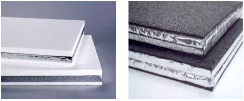
VIPs can reduce the thickness of wall more than existing insulating material while satisfying heat insulation performance. However, thermal bridge occurs by installation type or due to metal envelope that wraps panel, which lowers he heat insulation performance of wall. Therefore, it is a very important challenge to reduce thermal bridge to use VIPs more effectively. And when the heat insulation performance of VIPs-applied wall is evaluated, effective thermal transmittance (Ueff ) should be measured rather than unidimensional thermal transmittance. In the meantime, existing insulating materials or other materials such as rubber pad have also been applied to VIPs to prevent inner vacuum from being destroyed by external impact as well as thermal bridge of VIPs. (Figure 2)[8]
In this study, encapsulated VIPs was designed using existing insulating materials to prevent damage to metal envelope and reduce thermal bridge, and the performance was evaluated. Simulation for heat transfer was carried out on lineal thermal transmittance and effective thermal transmittance (U-value) of VIPs-wall.
2. The Characteristics of Vacuum Insulation Panels (VIPs)
2.1. Heat Insulation Performance of VIPs
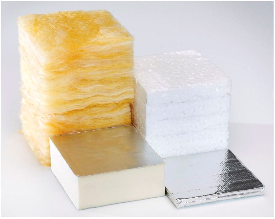
As seen in Figure 3[9], the thermal conductivity at the core of VIPs in initial stage of production ranged from 0.003 to 0.007 W/mK and this heat insulation performance is 3 to 9 times higher than that of existing insulating materials. Therefore, thinner VIP panels can be used while maintaining the same thermal transmittance as general insulating materials. Therefore, when VIPs are applied to a wall in place of general insulating materials, it can reduce outer wall thickness to 200∼300 ㎜, which is one tenth of the normal thickness, and also required for passive house and zero energy house.[7]
2.2. Thermal Bridge
Thermal bridge is an area where heat loss occurs due to the gap of thermal conductivity among the components of a structure. In a building, heat loss usually occurs toward where heat resistance is less due to the discontinuity of insulating materials.
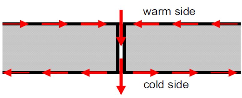
When VIPs are applied to wall, thermal bridge breaks out and it lowers the heat insulation performance of wall. As seen in Figure 4[10], thermal bridge occurs at the metal envelope that wraps the core and the gaps of the panels when applied to a building. Also, when VIPs are applied to a building, thermal bridge can take place in the adjacent materials (to VIPs) by applied type such as steel anchor, PVC, and wood, or occurs by the difference of thermal conductivity among VIPs.
3. Simulation Model (VIPs-Applied Wall)
3.1. Design of Encapsulated Vacuum Insulation Panels
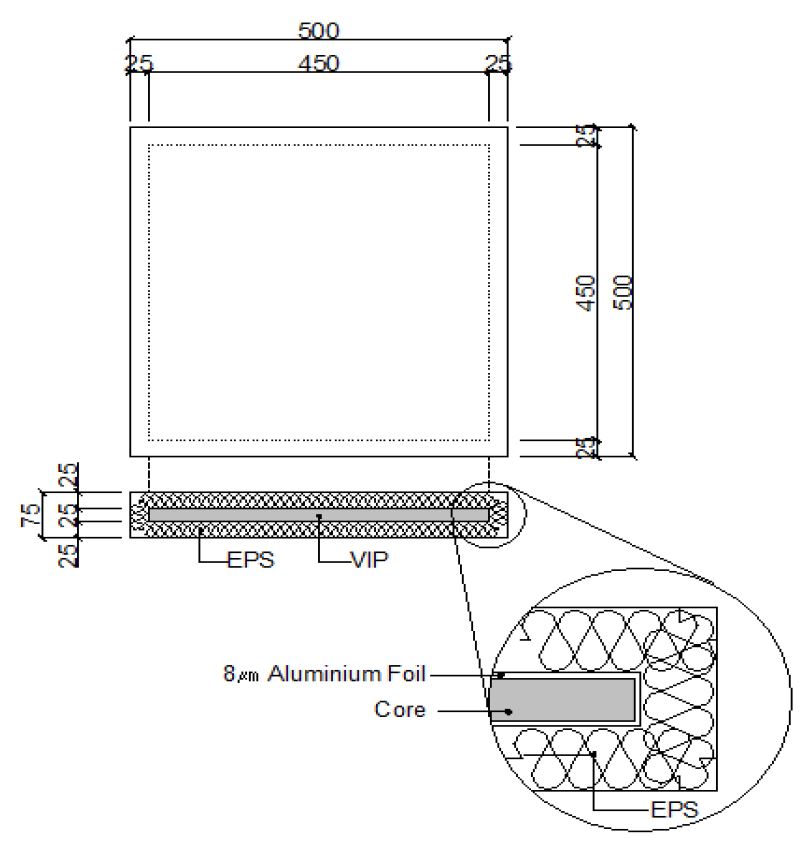
In this study, VIPs (450 x 450 x 25 ㎜) was used. And aluminium foil (8 ㎛ in thickness) was used as metal envelope, which is the main object to analyze for heat loss. As seen in Figure 5, EPS was used to design encapsulated VIPs to reduce the heat loss of metal envelope.
When EPS (existing insulating material) is encapsulated, bead method-based heat reserving board (2-class resistance to flame) was used to minimize the risk of fire to foaming polystyrene sound absorbing board, which is vulnerable to fire.
3.2. Simulation Model (Outer Wall)
To compare and evaluate the performance of encapsulated VIPs, this study applied both encapsulated VIPs and general VIPs to wall, simulated the heat insulation performance of wall, and compare and analyzed the results. To analyze the heat loss of VIPs metal envelope, the heat insulation performance of VIPs wall with and without metal envelope was compared and analyzed.
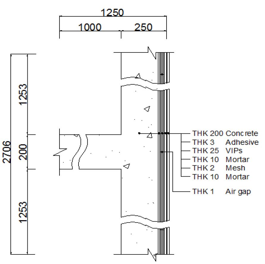
Outer wall and the area where floor borders on were chosen for the thermal performance analysis of general VIPs-applied wall. Considering heat loss that occurs in the gap between the panels, 1 ㎜ air layer was given to the interfaces (joints) of each wall. The modeling conditions for general VIPs-applied wall are as in Figure 6: VIPs (length 450 ㎜, thickness 25 ㎜), concrete slab (thickness 200 mm, 1000 ㎜ toward x axis), wall length (2706 ㎜ toward y axis).
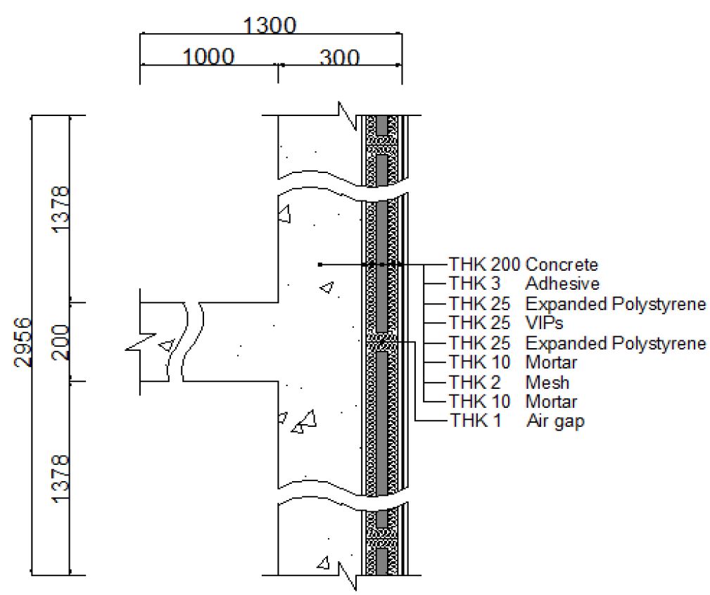
Figure 7 shows the modeling conditions of encapsulated VIPs-applied wall: VIPs (length 450 ㎜, thickness 25 ㎜), EPS (thickness 25 ㎜), concrete slab (thickness 200 ㎜, 1000 ㎜ toward x axis, wall length (2956 ㎜ toward y axis). When compared with Figure 7, wall length increased by 250 ㎜, as longer as EPS was added.
4. Simulation (Total Heat) and Result Analysis
4.1. Formulas: Lineal Thermal Transmittance and Effective Thermal Transmittance (U-Value)
ψ(psi): lineal thermal transmittance means heat transfer per the difference between unit length and unit temperature that is lost through the region of the concerned linear thermal bridge at normal state. Boundary condition(j) can be expressed like Formula (1).[11]
| Formula (1) |
ψ Lineal thermal transmittance (W/m·K)
L2d Heat conduction coefficient calculated by two-dimensional computation (W/m·K)
Uj Thermal transmittance of components j (W/㎡·K)
lj Length to thermal bridge (m)
Ueff : effective thermal transmittance (U-value) means heat transfer per the difference between unit area and unit temperature that is lost through the region of the concerned linear thermal bridge at normal state. Boundary condition(j) can be expressed like Formula (2). the effective thermal transmittance (U-value) of wall when lineal thermal transmittance is considered ing has higher value than that of thermal transmittance calculated by one-dimensional computation.[11]
| Formula (2) |
Ueff Effective thermal transmittance (U-value) (W/㎡K)
Ψ Lineal thermal transmittance (W/m·K)
U1d Thermal transmittance calculated by one-dimensional computation (W/㎡K)
lj Length to thermal bridge (m)
4.2. Simulation (Total Heat)
In this study, HEAT2 5.0[12] that can conduct two-dimensional heat transfer analysis at steady-state-condition was used to analyze the lineal thermal transmittance and effective thermal transmittance (U-value) of each wall. Thermal conductivity and heat capacity of materials by area for simulation were set like in Table 1 in accordance with BS EN ISO 6946:1997[13] and DIN V 4108-4[14] of German Standardization Organization (Deutsches Institut for Normung: DIN). And indoor/outdoor surface resistance of heat transfer and temperature was set like in Table 2 according to Energy Conservation Standard for Building[15].
4.3. Results of Simulations
According to simulation, the lineal thermal transmittance of general VIPs-applied wall is 0.2128 W/mK and effective thermal transmittance (U-value) is 0.2581 W/㎡K. When heat loss that occurred to VIPs metal envelope is excluded from the lineal thermal transmittance of general VIPs-applied wall, lineal thermal transmittance is 0.0926 W/mK and effective thermal transmittance (U-value) is 0.2136 W/㎡K. In the meantime, the lineal thermal transmittance of encapsulated VIPs-applied wall is 0.1304 W/mK and effective thermal transmittance (U-value)is 0.1852 W/㎡K. Table 3 summarizes the results.
When comparing the lineal thermal transmittance (0.2128 W/mK) of VIPs-applied wall reflecting the heat loss of metal envelope itself at the end part of VIPs with 0.0926 W/mK not reflecting it, lineal thermal transmittance turns out to increase by 130%. In addition, when comparing the effective thermal transmittance (U-value) (0.2581 W/㎡K) of VIPs-applied wall reflecting the heat loss of metal envelope itself at the end part of VIPs with 0.2136 W/㎡K not reflecting it, effective thermal transmittance turns out to increase by 21%.
The effective thermal transmittance (U-value) of general VIPs-applied wall is 0.2581 W/㎡K, which is 43% higher than one-dimensional thermal transmittance (0.1795 W/㎡K). The effective thermal transmittance (U-value) of encapsulated VIPsapplied wall is 0.1852 W/㎡K, which is 31% higher than one-dimensional thermal transmittance (0.1411 W/㎡K). The reason why the effective thermal transmittance (U-value) of encapsulated VIPs is lower than that of general VIPs in terms of incremental rate is that lineal thermal transmittance that generates in wall reduces when encapsulated VIPs is applied to wall.
The lineal thermal transmittance of encapsulated VIPs-applied wall is 0.1304 W/mK, which 39% lower than that of general VIPs-applied wall (0.2128 W/mK).
The effective thermal transmittance (U-value) of encapsulated VIPs-applied wall is 0.1852 W/㎡K, which is 28% lower than that of general VIPs-applied wall (0.2581 W/㎡K).
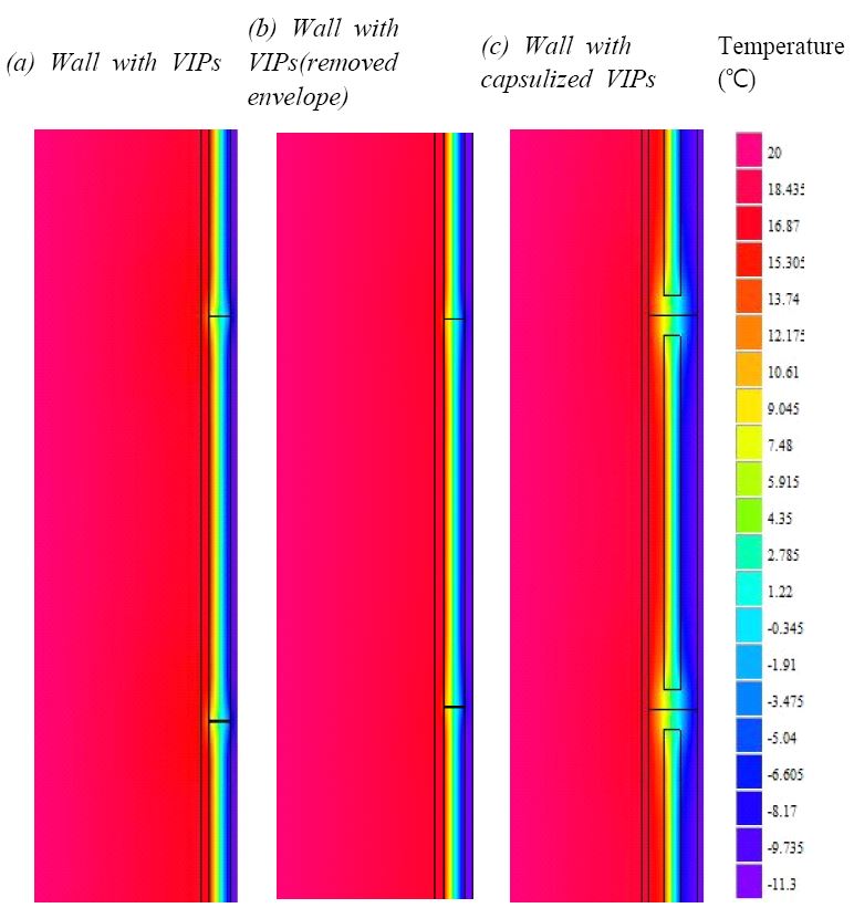
Figure 8 shows the temperature distribution of wall measured in the simulation. As heat loss occurred in the metal envelope of general VIPs, heat loss also broke out in the gaps of the panel interfaces, which changed the temperature distribution of wall at a considerable rate and caused thermal bridge.
5. Conclusion
To save the energy consumption of architectural sector, which is responsible for 25% of the total national energy consumption, the government has gradually stepped up heat insulation regulation. Accordingly, it is considered mandatary to introduce introduction of VIPs, which has far better heat insulation performance than general insulating materials, so that it can reduce the thickness of outer wall. To do so, thermal bridge is a challenge to get over to apply VIPs to wall. In this respect, the present study analyzed the heat insulation performance of VIPs-applied wall and brought forth conclusion as follows in an attempt to thermal bridge.
(1) As found in the simulation, when heat loss took places in the end part of VIPs due to the panel metal envelope, lineal thermal transmittance increased by 130% and effective thermal transmittance (U-value) increased by 21% more than the case where heat loss was not reflected. It indicates that total heat lost at the end part of metal envelope of VIPs has a great impact on the heat insulation performance of VIPs-applied wall.
(2) When VIPs were applied and EPS (existing insulating material) was used in encapsulated form, the lineal thermal transmittance of encapsulated VIPs-applied wall decreased by 39% more than that of general VIPs-applied wall. This can be explained by the reduced heat loss from metal envelope (8 ㎛ in thickness) when VIPs were encapsulated.
(3) When the effective thermal transmittance (U-value) of encapsulated VIPs-applied wall was compared with that of general VIPs-applied wall, it turned out that the effective thermal transmittance (U-value) of encapsulated VIPs-applied wall decreased by 28% more than that of general VIPs-applied wall. It is because encapsulated VIPs with EPS reduced thermal bridge that occurs to VIPs metal envelope and also reduced the one-dimensional thermal transmittance of wall.
(4) When the heat insulation performance of wall was calculated, the effective thermal transmittance (U-value) of general VIPs-applied wall and encapsulated VIPs-applied wall turned out to have increased by 43% and 31%, respectively, more than one-dimensional thermal transmittance. It indicates that total heat lost due to thermal bridge when VIPs are applied to wall has a great impact on the heat insulation performance of wall.
(5) When the metal envelope of VIPs is damaged by external impact, inner vacuum can be destroyed, which drags down heat insulation performance obviously. In addition, the heat insulation performance of wall decreases due to the gaps that are made when VIPs are applied to wall and the thermal characteristics of metal envelope. To minimize this problem, this study used and made bead method-based insulating material (2-class resistance to flame) into encapsulated form. When encapsulated VIPs are applied to wall, it is expected to minimize the damage risk to metal envelope and thermal bridge of wall.
With the findings of this study, additional research needs to follow the present study to conduct mock-up test on VIPs-applied wall and 3-dimensional thermal performance analysis.
Acknowledgments
This work was supported by the International Collaborative Energy Technology R&D Program (No. 20148520011270) and Human Resources Program (No. 20134010200540) of the Korea Institute of Energy Technology Evaluation and Planning (KETEP) granted financial resource from the Ministry of Trade, Industry & Energy, Republic of Korea.
References
- Korean Ministry of Land, (2014), Infrastructure and Transport, Activation Plan of Zero Energy Building Response to Climate Change.
-
Alam, M., Singh, H., and Limbachiya, M.C., (2011), Vacuum Insulation Panels (VIPs) for building construction industry - A review of the contemporary development and future direction, Applied Energy, 88(11), p3592-3602.
[https://doi.org/10.1016/j.apenergy.2011.04.040]

-
박시현, 임재한, 송승영, “공동주택 습식 진공 외단열시스템 성능 평가”, 한국생태환경건축학회 논문집, 13(6), (2013).
Park, S. H., LIm, J. H., and Song, S. Y., (2013), Performance evaluation of adhesively fixed external insulation and finish system using Vacuum Insulation Panels for apartment building, Journal of the Korea Institute of Ecological Architecture and Environment, 13(6), p45-53. -
Simmler, H., and Brunner, S., (2005), Vacuum Insulation Panels for Building Application Basic Properties, Aging Mechanisms and Service Life, Energy and Building, 37(11), p1122-1131.
[https://doi.org/10.1016/j.enbuild.2005.06.015]

-
Ghazi, K., Bundi, R., and Binder, B., Effective thermal conductivity of vacuum insulation panels, Building Research & Information, 32(4), p293-299, (2004).
[https://doi.org/10.1080/0961321042000189644]

-
박세현, 김진희, 김준태, “진공단열패널 외피를 위한 설치방법에 따른 열교부위의 선형열관류율 분석, 한국감성과학회, (2012).
Park, S. H., Kim, J. H., and Kim, J. T., (2012), Linear thermal transmittance of thermal bridge at building envelopes with VIPs, Korean Society for Emotion and Sensibility. -
송승영, 박시현, 구보경, 임재한, 류성룡, “패시브 및 제로에너지 공동주택을 위한 진공단열재 적용 건식 외단열시스템 성능평가”, 대한건축학회 논문집, 29(09), (2013).
Song, S. Y., Park, S., Koo, B. K., Lim, J. H., Ryu, S. R., (2013), Performanco evaluation of EIFS Using Vacuum insulation panels for passive and zero-energy apartment building, Architectural institute of Korea, 29(9), p219-229. - http://www.vacutherm.co.uk/s/cc_images/teaserbox_2452000957.jpg?t=1438351379 and http://oisd.brookes.ac.uk/ivisnet/images/VacuporR-RPsml.jpg.
- http://www.ribaproductselector.com/docs/9/26829/external/images/GA5247.jpg.
- Simmler, H., Brunner, S., Heinemann, U., and Schwab, H., (2005), High Performanco Thermal Insulation IEA/ECBCS Annex 39(Subtask A-B), ECBCS Annual report.
- EN ISO 10211-1, (2007), Thermal bridges in building constructio n, Calculation of heat flows and surface temperatures.
- Blomberg, T., (2000), HEAT2 5 - A PC-program for heat transfer in two dimensions, Manual with brief theory and example, Buildingphysics.
- BS EN ISO 6949, (1997), Building Components and Building Elements - Thermal Resistance and Thermal Transmittance - Calculation Method.
- DIN V 4108-4, (1988), Thermal Insulation and Energy Conservati on in Buildings - Part 4: Characteristic Value relating to Thermal Insulation and Protection Against Moisture.
- Korean Ministry of Land, Infrastructure and Transport, (2014), design standard of energy conservation in buildings.
