Characteristic of indoor air quality according to ventilation in a temporary residential building
ⓒ Copyright Korea Institute of Ecological Architecture and Environment
Abstract
Recently, natural disasters have unexpectedly occurred at various places in the world and the countermeasure of them become the social issues. Many of victims in disasters need temporary residential facilities above all things and many of researches have been conducted in order to develop simple, safe, and economic designs of them. Moreover, indoor thermal comfort and air quality must be considered in the facilities against a disaster, because clean and healthy space should be provided to the suffered victims. In this research, in order to estimate the indoor environment of the developed modular building for disaster preparation, CFD simulation was conducted in the various condition. In this paper, indoor air quality such as the age of air, the concentration of CO2 was estimated by the case study
Keywords:
CFD, Age of air, Indoor air quaility1. Introduction
1.1. Background and Purpose
Large-scaled natural disasters have recently been more observed due to global warming and abnormal changes of climates. Accordingly, countermeasures are drawing more attention than before to reduce the social loss caused by them. In particular, it is required that policy and technology be prepared to protect the victims of natural disaster, so who lost residential space, and provide them with pleasant temporary residential building quickly. As temporary residential building is commonly perceived as a short-term shelter for sufferers from natural disaster until new residential space is prepared, it is considered that such structure needs just basic dwelling equipment and facility for temporary living. According to a precedent study(1), however, the victims have high level of demand for pleasant residential environment. Therefore, temporary residential building should be provided with proper indoor hygiene and air quality. To do so, when temporary residental building is designed, construction factors should be placed in consideration in terms of both planning and facility. In addition, it is also required to develop a method by which the indoor air quality can be qualitatively analyzed (numerical analysis) to improve the environment of temporary residential model. In Korea, Lee et al(2) measured the indoor air quality of apartment housing by finish material using CFD and Kim et al(3) derived the qualitative data of indoor air quality in apartment building by ventilation, using CFD simulation. Abroad, Li et al(4) analyzed wind flow rate, temperature and air age when a wall-mounted air-conditioner is equipped in a bed room in order to make a pleasant living environment for room occupants. Weiwel et al(5) analyzed the pattern of indoor air diffusion of floor-standing type room air-conditioners in office building and suggested the control system. However, few studies have been conducted on indoor air environment for temporary residential space using CFD. The development of temporary residential building with optimized functions requires first designing spatial model that can be assembled and dissembled and proper placement of facility elements and specifications in the designed model. And then a technique that can analyzes indoor air quality qualitatively should be used in reviewing the developed model.
The present study is aimed to carry out a variety of tests on a temporary residential building to develop by using CFD simulation and analyze the indoor environment by amount of ventilation and setting condition of inlet and outlet. In this study, the results of CFD analysis of indoor environment on the suggested model are described.
2. Summary of Research Space and Analysis Method
2.1. Research Space
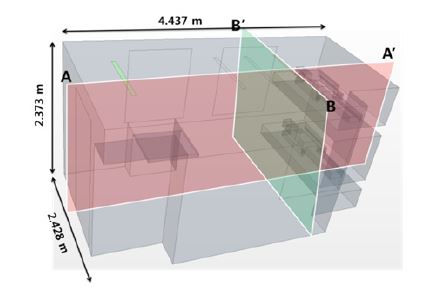
In this study, evaluation of interior spatial environment was conducted on a temporary residential modular (both attachable and detachable) model for victims of natural disaster. The model is designed to be for 2 persons in size of 5 m × 3 m, in which a foldable table, bed and some furniture are equipped. The analytical model is summarized in 3D in Fig. 1. The space to be analyzed includes indoor space (4.437 m × 2.428 m × 2.373 m) except the walls and adopts a body model of two room occupants lying on a bed.
2.2. Analysis Method
To examine the air environment of temporary residential model, a commercial CFD analytic tool (STAR CCM+) was used in this study to analyze air current field, CO2 concentration distribution and age of air. k-ε turbulence model was employed to conduct indoor air current analysis and calculation was performed under normal conditions. In addition, an assumption was made that indoor heat and pollutants only come from the body and respiration of a room occupant . Thus they were set to 100 W from body heat and CO2 of 500 L at 40,000 ppm/hour from the exhalation on a face area (0.03 m2)(6). As indoor environment, -5℃ was set as outdoor temperature and floor heating system was applied to maintain 22% of pleasant temperature in the temporary residential model. Outlet air temperature was supplied to maintain about 16℃ in a stable condition where 25% of outdoor air temperature and 25% of recycled air are mixed. Table 1 shows the boundary condition of simulation of the temporary residential model.
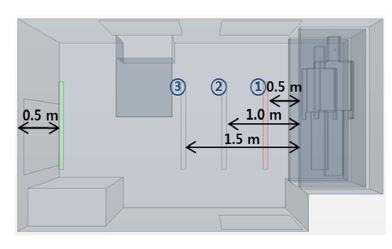
Amount of ventilation was set to Ministry of Transportation(0.5 times/hr)(7) as base case and it was compared with 2.35 times/hr based on the per-capital amount of ventilation (30 m3/hr per capita))(8) of the Enforcement Ordinance of Japanese Construction Standard Law to analyze the indoor environment of temporary residential model by amount of ventilation. For the position of diffusers (air inlet/outlet), air outlet was fixed near the entrance of the temporary residential model, which was distant from a resident since pollutants are more concentrated around air outlet in general while air inlet was positioned 0.5 m, 1.0 m and 1.5 m off from the resident's sleeping space, respectively, under the logic that heat-exchanged fluid are supplied in linear and circular form. With these settings, indoor air quality was measured by location and shape of air inlet/outlet. Fig. 2 shows the shapes and locations of the diffusers in the temporary residential model. And Table 2 shows the case conditions to analyze, including the shapes and wind velocity of diffusers and amount of ventilation of the temporary residential model.
3. Indoor Environment Analysis by Diffuser Setting
3.1. Indoor Environment Analysis by Shape and Amount of Ventilation of Diffusers
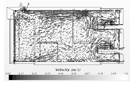
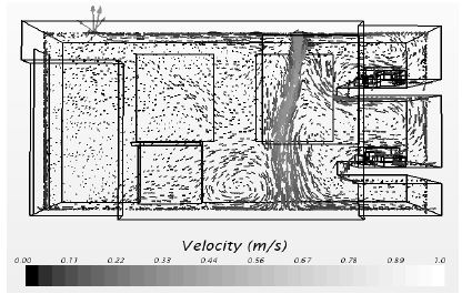
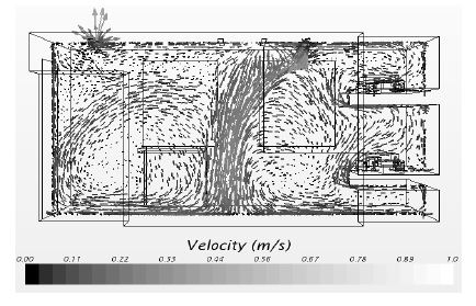
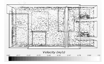
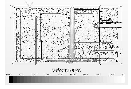
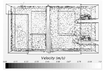
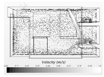
Fig 3 to 6 show the air current fields of a temporary residential model by the shape and amount of ventilation of diffuser. Fig. 3 and 4, and Fig. 5 and 6 show the changes of air current field by the shape of diffuser when amount of ventilation is was 0.5 times/hr. and 2.35 times/hr, respectively. Because air supply velocity is determined by amount of ventilation per hour and size of diffuser in each case, air velocity is slowest in Case 1 in which amount of ventilation is small and surface for air supply is broad while air velocity is fastest in Case 2 where amount of ventilation is large and surface for air supply is narrow. Since the average indoor air current velocity turns out to be 0.01 m/s ∼ 0.22 m/s(9), which is satisfactory, air-supplied fluid in Case 1 with small air current velocity exhausts without being circulated due to buoyancy and short circuit. Also, in Case 2 to 4, air-supplied fluid contacts human body directly so that a room occupant may feel uncomfortable because air current velocity is great. Table 3 shows the average wind velocity and temperature of diffusers by case.
For the analysis of indoor CO2 concentration, it was assumed in simulation that 2 residents lie on a double-deck bed. The concentration of CO2 that is generated from a room occupant was set to 40,000 ppm, which is a general value of CO2 per person, at 500L/hr. of amount of breathing per person. For human body model, the occurrence area of CO2 was set to 0.03 m2 and CO2 concentration of inflow air flux was set to 400 ppm.
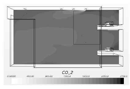
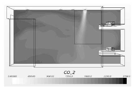
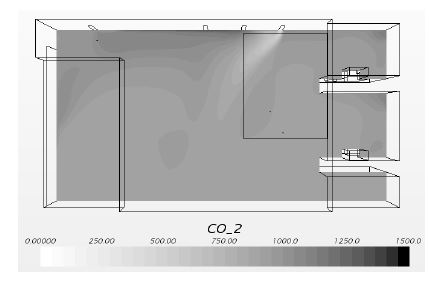
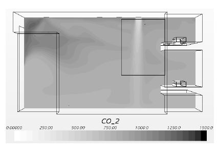
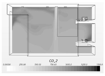
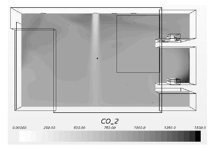
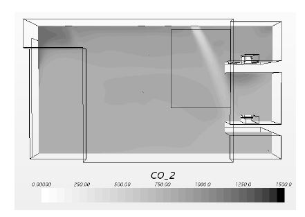
Fig. 7 to 10 show the distribution of CO2 concentration in the temporary residential model by the shape of diffuser and amount of ventilation. The average CO2 concentration of Case 1 to 4 turned out to be 2156 ppm, 2035 ppm, 929 ppm and 850 ppm, respectively. Fore reference, Public Health Control Act and Construction Law stipulate that indoor CO2 concentration shall remain below 1000 ppm(10). However, the average indoor CO2 concentration of the temporary residential model was above 2000 ppm when the amount of ventilation was 0.5 times/hr because it was lower than amount of CO2 exhaust, which does not meet the guideline recommended by law. On the other hand, when amount of ventilation was 2.35 times/hr, the average indoor CO2 concentration stayed below 1000 ppm, which satisfies the criteria for indoor CO2 concentration.
Air age is an indicator of the time duration that air coming in through an air supply diffuser remain remains inside of a building. air fed from outside through the inlet goes through several courses until a certain point P. here, P is called local mean age and change of air concentration is measured at P.
The present study assumed that the entire space discharges a certain amount of gas in the analysis space and calculated the time duration that air coming in through an air supply diffuser remain remains inside. Using Equation (1), this study computed air age at a random point P (Ap) and used Equation (2) to get nominal time constant (m)9).
| (1) |
| (2) |
Here, C is the concentration of pollutants (kg/m3); q is amount of pollutants generated per unit volume (kg/m3s); and V is net volume of the temporary residential space (m3).
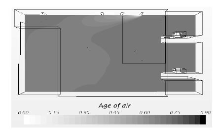
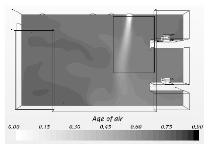
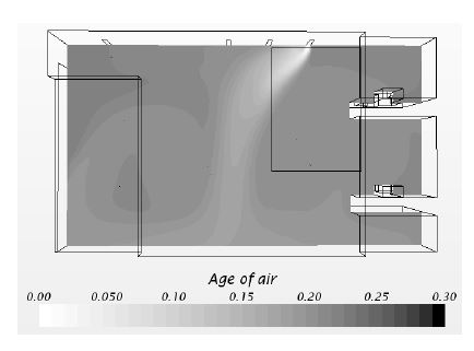
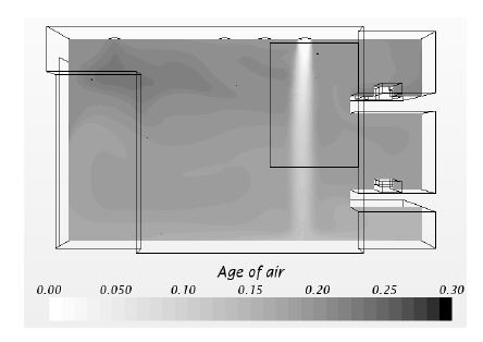
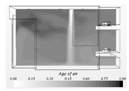
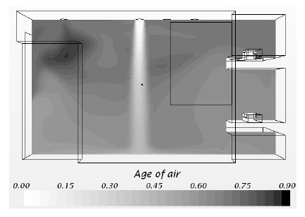
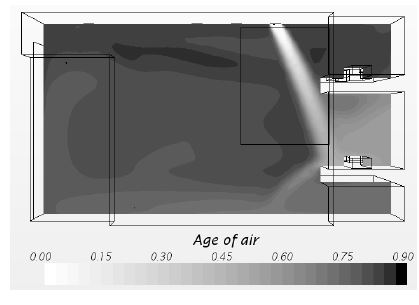
Fig. 11to 14 show the distribution of air age on A-A' section of the temporary residential model by the shape of diffuser and amount of ventilation. Since Case 1 has slow wind (air current) velocity, fresh air can't not reach an room occupant but exhausts. However, air age turns to be high along the entrance (the left door) of the temporary residential model and the ceiling side in Case 2 to 4. While air-supplied fluid reaches the floor and distributes fresh air in Case 4, air age of Case 3 turns out to be high around the exhaust diffuser because air-supplied fluid circulates around the entire room.
3.2. Indoor Environment Analysis by the Location of Diffuser
Fig 15 and 16 show the indoor air current fields of the temporary residential model by the location of diffuser. It was set for each case that a circle-typed air supply diffuser was located 0.5 m 1.0 m 1.5 m off from an occupant's sleeping room, respectively and air was supplied. In this study, it turned out that the indoor air current field was similar by the location of air supply diffuser. Table 4 shows the average wind velocity and temperature of the air supply diffusers in each case.
Fig. 17 and 18 show the distribution of CO2 concentration on A-A' section of the temporary residential model by the location of air supply diffuser. The results of this analysis shows that the closer the air supply diffuser is to an occupant, the higher CO2 concentration around the device is. In addition, CO2 concentration around an occupant that uses the upper bed of the double-deck bed is higher than that around an occupant who uses the lower bed of the double-deck bed. The average indoor CO2 concentration of Case 4 to 6 turned out to be 850 ppm, 830 ppm and 883 ppm, respectively and average indoor CO2 concentration is lowest at the point where the air supply diffuser is 1 meter off from an occupant.
Fig. 19 and 20 shows the distribution of air age on A-A' section of the temporary residential model by the location of air supply diffuser. The results of this analysis show that rapidly supplied fresh air fails to reach up to an occupant due to rapid wind velocity in Case 4 where the air supply diffuser is located closest to an occupant. Especially, air age turns out long around an occupant tat uses the upper bed of the double-deck bed. The analysis of air age by the location of air supply diffuser shows that local mean age is short when inlet is located at the center of a room, so is air age around an occupant.
3.3. Indoor Environment analysis by the Direction of Wind
Fig. 21 shows the indoor air current field when the direction of air current of the air supply diffuser is 60°. Compared with vertical air supply at 60°when amount of ventilation is 2.35 times/hr, indoor air fluid moves similarly. However, when air is supplied at 60°, an occupant tend to be less pleasant because supplied air fluid reaches an occupant on the lowe bed of the double-deck bed directly. In addition, it was confirmed that the average temperature of air supply/exhaust diffuser rose by more than 1℃. Table 5 shows the average wind velocity and temperature of air supply/exhaust diffuser.
Fig. 22 shows the distribution of CO2 concentration on A-A' section of the temporary residential model when the direction of air inflow of the air supply diffuser is 60°. The analysis of the average indoor CO2 concentration shows that when the direction of air supply is 60°, the average indoor CO2 concentration is 836 ppm, which is lower than that in Case 4, but CO2 concentration around an occupant is higher.
Fig. 23 shows the distribution of air age on A-A' section when the direction of air supply is 60°. The analysis of air age by the direction of air supply shows that air age is high in all the indoor space but the periphery of an occupant that uses the lower bed of the double-deck bed when the direction of air supply is 60°. Particularly, air age around an occupant that uses the upper bed of the double-deck bed is higher.
4. Conclusion
The present study carried out CFD simulation on the temporary residential model to examine the change of air quality by the shape of diffuser and amount of ventilation. The findings of this study is summarized as follows.
- (1) The analysis of air quality by amount of ventilation shows that the average indoor CO2 concentration is above 2000 ppm at the setting of 0.5 times/hr. of amount of ventilation and two occupants because amount of ventilation is lower than the CO2 exhaust (from two occupants) and it does not meet the guideline set by law.
- (2) The analysis of air quality by the location of diffuser shows that the indoor air current environment is similar by location, but local mean age is short when air supply diffuser is located at the center of a room, and especially air age around an occupant is shorter.
- (3) The analysis of indoor environment (air quality) by the direction of air supply shows that the average indoor CO2 concentration at both vertical air supply and 60°is similar: 850 ppm and 836 ppm, respectively), but CO2 concentration around an occupant different: CO2 concentration around an occupant is higher at 60°air supply than at vertical air supply. The analysis of air age by the direction of air supply shows that air age is high in all the indoor space but the periphery of an occupant that uses the lower bed of the double-deck bed when the direction of air supply is 60°.
The temporary residental model, which is the research object of this study, was designed with priority on quick delivery, connection and assembling. Therefore, when roon density is placed into consideration, it is thought that there is room for further improvement in this study.
Acknowledgments
This research have been conducted as part of 2013 own project of Korea Institute of Energy Research (B3-8413) and by support of 2014 research fund for the New Professor Research of Pusan National University.
References
- Kim, Seoung-Soo, Lee, Sang-Ho, A study for infra construction of temporary residential districts from disasters, Conference of Architectural Institute of Korea, (2009).
- Lee, Eun-Jung, Ryu, Young-Hee, Lee, Kyung-Hoi, Simulation and Measurement of Indoor Air Quality in Apartment Housing by CFD, Journal of Architectural Institute of Korea, 23(1), p231-238, (2007).
- Kim, Seok-Keun, Yee, Jurng-Jea, The Effects to Indoor Air Quality as Ventilation System Operation in Apartment House Using CFD Simulation, Journal of SAREK, 19(2), p142-148, (2007).
-
Li, Yang, Miao, Ye, Bao-Jie, he, CFD simulation research on residential indoor air quality, Science of The Total Environment, 472, p1137-114, (2014).
[https://doi.org/10.1016/j.scitotenv.2013.11.118]

-
Weiwel, Liu, Zhiwei, Lian, Ye, Yao, Optimization on indoor air diffusion of floor-standing type room air-conditioners, Energy and Buildings, 40(2), p59-70, (2008).
[https://doi.org/10.1016/j.enbuild.2007.01.010]

- Jeong, Gwang-Seop, Kim, Kwang-Woo, An, Byeon-Guk, Park, Byeong-Yun, Lee, Jeong-Jae, Bang, Seung-Gi, Kim, Soo-Jin, Jeong, Yong-Ho, Building air-conditioning equipment, Seongandang, (2012), p310.
- Ministry of Transportation jeongchaekgwan construction, construction business handbook, (2013), p107.
- Tanaka, Shunroku, Takeda, Hitoshi, Adachi, Tetsuo, latest architectural environment engineering, Inoue Shoin, (2003), p147.
- Lee, Jong-Chan, Park, Young-Ho, Kim, Byung-Sean, Lee, Samg-Ho, A Case Study on the Analysis and Reform Measure of Indoor Ventilation in the Super High-Rise Apartment Housing with Using CFD, Journal of Architectural Institute of Korea, 25(7), p321-328, (2009).
- Lee, Jeong-Jae, Geum, Jong-Su, Do, Geun-Young, Kim, Sang-Jin, Kim, Jong-Min, Kim, Hwan-Yong, Lee, Sun-Yeong, Park, Hee-Ouk, Kim, Jea-Dol, Kim, Yong-Gyeong, Built Environment Engineering, Sigma Press, (2004), p249.
- C. Buratti, R. Mariani, E. Moretti, Mean age of air in a naturally ventilated office: Experimental data and simulations, Energy and Buildings, 43(8), p3.32-2027, (2011).
- Chae, Ho-Byung, Nan, Yujin, Sung, Min-Ki, Kim, Jong-Hoon, Analysis of a indoor environment for a modular building using CFD simulation, Winter Conference of SAREK, p219-222, (2013).
