Exploiting Waste Heat from Building HVAC Systems via Power Generation
ⓒ 2020. KIEAE all rights reserved.
Abstract
Power generation by utilizing waste heat (<60℃) from various HVAC systems, especially heat pump (air conditioning) units, was considered in conjunction with the operation of triboelectric nanogenerators (TENGs) of two different shapes, driven by a thermomagnetic engine exploiting the magnetocaloric effect of gadolinium (Gd). Gadolinium is a material whose magnetic property experiences a transition from ferromagnetic to paramagnetic near 20℃ (known as its Curie temperature).
An energy harvester comprised of a thermomagnetic engine and two differently shaped triboelectric nanogenerators (C-TENG, D-TENG) was designed and constructed, whose power output was monitored as the engine ran at different temperatures of the heat source (waste heat) while that of the heat sink was maintained at 18.5℃.
The thermomagnetic engine produced its highest rotational speed of 211 rpm at a temperature difference of 45℃ between hot and cold water jets. An output voltage and current of 23 V and 10 µA, respectively, were obtained when the outputs from both TENGs were rectified and added together, which demonstrates the potential of using TENGs in conjunction with harnessing waste heat from building HVAC systems if the scale-up of the engine as well as the generators is achieved appropriately.
Keywords:
Waste heat, HVAC system, Thermomagnetic engine, Triboelectric nanogenerators, Power generation, Sustainability1. Introduction
At present, energy security is a major concern due to ever growing energy demands. According to one report, global energy demands could increase by 50% by 2030, which will lead to a greater shortage of energy reserves in the coming decades. A massive source of energy savings could be obtained by the reduction of waste heat, especially, from building HVAC systems. This source exists all around the world in different forms[1], and this would cause a valuable reduction in greenhouse gas emissions. A cost effective method to harvest this waste energy can make a considerable contribution towards the solution of energy crisis and environmental pollution. Undoubtedly, many researchers have raised their concerns about climate change, and immense efforts have been made to utilize the waste heat for power generation. Using the thermomagnetic effect is one of the most popular methods used to convert heat into mechanical (electrical energy). The devices used for this purpose exploit the transition effect of rare earth magnetic material to generate electricity near room temperature. Many patents were issued in the 19th century describing the fact that heat alters the magnetic properties of ferromagnetic materials and results in mechanical (electrical) power generation[2-5]. In 1984, Kirol carried out some experiments to investigate the performance of thermomagnetic generators for three working magnetic materials and achieved perfect regeneration[6]. Ujihara proposed an efficient and different design for small-scale application using piezoelectric materials[7]. Solomon conducted experiments by cycling the magnetic field and achieved improved performance by using a Y2(FexCo1-x)17 alloy[8 9]. Srivastava suggested a multiferroic Heusler alloy (Ni45Co5Mn40Sn10) as an alternative magneto caloric material for thermomagnetic devices [10]. Some other thermomagnetic energy conversion devices reported in the literature are Takahashi’s model[11, 12], the van der Mass Curie-point motor[13] and the Murakami rotary thermomagnetic motor[14]. Stauss proposed a thermomagnetic model with conventional ferromagnetic materials and predicted the maximum efficiency using Weiss’ theory of ferromagnetism[15]. In short, scaling of a higher-power thermomagnetic generator can be addressed once the basic understanding of efficient design has been developed.
The aim of this work was to recheck the performance reported in the literature and to explore the potential of energy harvesting technology. An attempt was made to develop a novel thermomagnetic generator design that can work in conjunction with a triboelectric nanogenerator to harvest waste heat and convert it into electricity. The designed thermomagnetic engine uses gadolinium as a working transition material. Gadolinium (Gd) is a rare earth ferromagnetic material[16] that changes its magnetic property when heated above and below the Curie temperature. Gadolinium has a Curie temperature of 20℃, which makes it a suitable magnetocaloric material for low-temperature operations. Gadolinium shows a paramagnetic nature when a hot water jet impinges on it, whereas it becomes ferromagnetic when a cold water stream impinges on it. This change in the magnetic property interacts with the permanent magnet and produces rotational mechanical energy. To exploit the mechanical energy derived from low-grade thermal energy, two different shapes of triboelectric nanogenerators have been deployed to convert mechanical energy into electrical energy at the same time. The triboelectric effect is an old but extremely effective phenomenon to harvest different types of mechanical energy, such as wind power[17,18], ocean flow[19,20], rain drops[21] footfalls[22] and so forth. It provides an unprecedentedly cost-effective means of energy conversion by coupling electrostatic induction and the triboelectric effect[23].
The proposed thermomagnetic engine was designed to convert waste heat into mechanical energy, and then the proof of concept was ensured by its final conversion to electricity by using a triboelectric generator. The thermomagnetic engine was tested for various temperatures between hot and cold water sources. When the temperature difference reaches 45℃ between the hot and cold water jets, the proposed engine produces its highest rotational speed of 211 rpm. Under a rotational speed of 211 rpm, D-TENG achieves excellent performance with a short-circuit current of 1.4 µA and an open-circuit voltage of 8.9 V. The C-TENG produces a short-circuit current and an open-circuit voltage of 8.8 µA and 14.2 V, respectively, when spinning at the same rotational speed. The outputs of both the C-TENG and D-TENG were added in order to obtain maximum efficiency in conjunction with the operation of thermomagnetic engine. Moreover, the designed generator produces a maximum DC power output of 12.2 µW at a loading resistance of 1 MΩ.
2. Design and Fabrication
2.1. Design and Fabrication of Gadolinium-based Thermomagnetic Engine
A novel thermomagnetic engine design is proposed that exploits the transition effect of gadolinium to harvest waste heat energy.
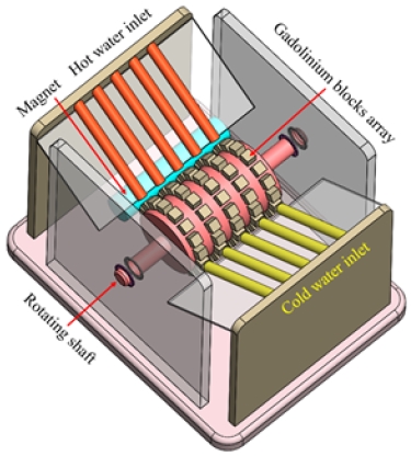
The engine comprises a cylindrical rotor, permanent magnet, and three water nozzles. The rotor is 66 mm in diameter with sixteen equally spaced cubical holes, where gadolinium blocks with dimensions of 1 cm × 1 cm × 1 cm are mounted. The permanent bar magnet with dimensions of 10 cm × 2.5 cm × 1 cm is placed at a 1-mm distance from the rotating cylinder. The three water nozzles are placed at an angle of 120° from each other. Of these, one is a hot water jet, which is placed on the same side of the bar magnet, while the other two cold water jets are placed at the opposite side of the magnet. A total schematic view of the proposed energy harvester is shown in Fig. 1.(a), whereas its core component, the Gd based thermomagnetic engine, is given in Fig. 1.(b).
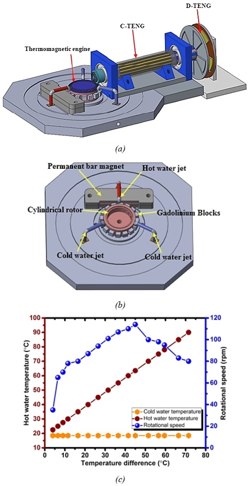
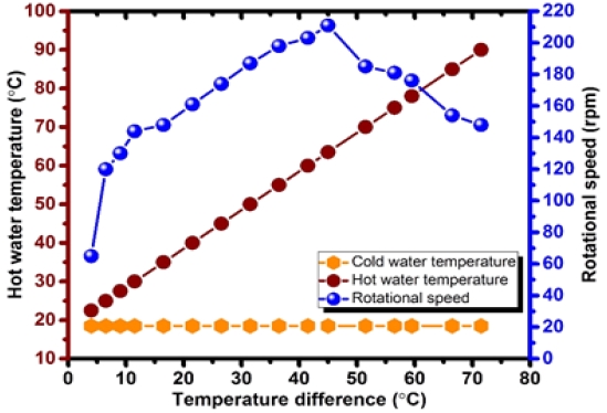
(a) Total schematic view of energy harvester coupled with both C-TENG and D-TENG, (b) Schematic of thermomagnetic engine. (c) Rotational speed vs. temperature difference between cold and hot water jets
Heat alters the magnetic properties of gadolinium, so when a hot water stream hits gadolinium it becomes paramagnetic, which interacts with the permanent magnet, and it is pulled away towards the cold water stream, where it returns to its ferromagnetic nature. The cycle continues, and the temperature difference between the hot and cold water jets produces rotational mechanical energy. A series of measurements were made to monitor the rotational speed (rpm), while the flow rate and temperature of the hot and cold water jets were controlled. The temperature of the cold water jet was maintained at 18.5℃ whereas for the hot water jet, a range of temperatures was tested from 22.5℃ to 90℃. When the temperature between the two jets differed by 4℃, a minimum rotational speed of 35 rpm was observed. Meanwhile, a maximum rotational speed of 114 rpm was achieved with a temperature difference of 45℃ between the two jets. However, a further increase in the temperature difference beyond 45℃ resulted in a decrease in the rotational speed as described in Fig. 1.(c). This might be due to the limited time interval for the heated gadolinium blocks to cool off and return to their ferromagnetic nature. It should be noted here that the experiment was carried out at a constant flow rate of 293 mL/min, controlled by using Lab Companion (RW-3025G).
2.2. Design and Fabrication of Triboelectric Generator
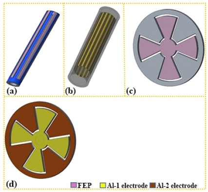
As previously mentioned, two different shapes of triboelectric nanogenerator were designed and integrated with the thermomagnetic engine. Of these, one was a cylindrical triboelectric nanogenerator (C-TENG), and the other was a rotating disk-shaped triboelectric nanogenerator (D-TENG). The C-TENG consisted of a 22-cm-long hollow cylinder, which was fabricated by using a 3D printer. The inner and outer diameters of the cylinder were 18 mm and 30 mm, respectively. An FEP film was used as an active triboelectric surface, and 7 strips of FEP were fixed to the outer surface of the cylinder, which made the rotor of the C-TENG as shown in Fig. 2.(a). Similarly, an 18-cm-long hollow cylinder was designed, and 7 pairs of aluminium strips were fixed on the inner surface of the cylinder, which made the stator of the C-TENG as shown in Fig. 2.(b). The inner and outer diameters of the stator cylinder were 20 mm and 34 mm, respectively. The optimum gap between the active triboelectric surface (FEP strips) and aluminium was selected to be 1 mm for the C-TENG. The disk-shaped triboelectric nanogenerator (D-TENG) also comprised a rotor and stator, which were made by employing a 3D printer and a laser cutter, respectively. The rotor was an acrylic segmented disk with a diameter of 120 mm, and it was used as a substrate for the FEP films. The stator of the D-TENG was fabricated from 1-mm-thick aluminium plate and adjusted to have a 1-mm gap from the rotor of the D-TENG after careful analysis of the output voltage and the rotational speed. Schematic drawings of the rotor and stator parts of the D-TENG are shown in Fig. 2.(c) and 2d. 1 mm was chosen for the spacing of the both TENGs as larger air gaps result in a decline of their output performance. On the other hand, an air gap smaller than 1 mm is difficult to maintain for free-standing operation of the TENG.
2.3. Design and Fabrication of Thermomagnetic Generator
As described earlier, the designed thermomagnetic engine achieved its maximum rotational speed of 114 rpm at the temperature difference of 45℃ between the hot and cold water jets. To further increase the rotational speed of the engine, a 3:1 nylon bevelled gear of 66 mm and 18 mm in diameter was connected with the rotating cylinder of the thermomagnetic engine. Subsequently, the rotor of the C-TENG was integrated with the secondary gear followed by the rotor of the D-TENG. The prototype of the operational device is shown in Fig. 3. The rotational speed of the thermomagnetic generator was tested for various temperatures after it was connected with a pair of gears and rotors of both the D-TENG and C-TENG. As explained earlier, the cold water was kept at a constant temperature of 18.5 ℃, while that of hot water was raised from 22.5℃ to 90℃ to measure the rotational speed. The maximum rotational speed of 211 rpm was measured at the temperature difference of 45℃ between the hot and cold water jets as seen in Fig. 4.
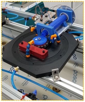
Prototype of the designed thermomagnetic engine integrated with C-TENG and D-TENG (energy harvester)
3. Results and Discussion
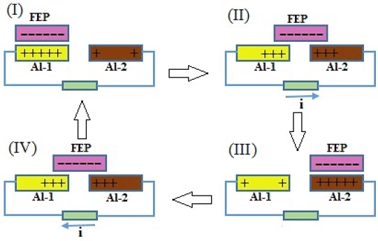
The operation of two different types of triboelectric nanogenerators (C-TENG, D-TENG) in a non-contact sliding mode was experimentally investigated to explore the conversion of the rotational mechanical energy into electrical energy as the waste heat from the building's HVAC systems drove the thermomagnetic engine developed in the present work by using a number of Gd blocks. The electrical energy produced from the mechanical energy is divided into two parts: 1) energy produced by the C-TENG and 2) energy produced by the D-TENG. The energy generation process of both TENGs is schematically depicted in Fig. 5, which takes place through four motion steps. In the first step (I), the fluorinated ethylene propylene (FEP) film adhered on the rotors of both the C-TENG and D-TENG are aligned with the aluminium electrodes, resulting in an equal distribution of positive and negative charges on the Al-1 electrode and FEP surfaces, respectively, due to the different polarities of the two triboelectric surfaces. In the following step, the positive charge transfers from Al-1 to Al-2 when the FEP segment moves to the middle position between two electrodes (step-II). Thus, electrons transfer from Al-2 to Al-1, leading to the output current in the external circuit.
As the FEP comes to the overlapping position of Al-2, the bulk of the electrons moves to Al-1, which results in the majority of the positive charges being left on Al-2 (step III). Finally, the FEP segment starts to move towards the adjacent Al-1 electrode. Thus, the electrons travel back from Al-1 to Al-2, generating an output current directed opposite to that of the previous step (step IV).
The electrical power output of both the C-TENG and D-TENG were studied as the thermomagnetic engine was operated at its maximum rotational speed of 211 rpm. At this speed, the C-TENG produced the respective values of 14.2V and 8.8µA for its open-circuit voltage and short-circuit current. Meanwhile, the D-TENG gave an open-circuit voltage and short-circuit current of 8.9 V and 1.4 µA, respectively, with a gap of 1 mm between the rotors and stators. The output performance of both the C-TENG and D-TENG are presented in Fig. 6. The output performance of both TENGs is also analyzed in relation to the rotational speed range of 144 to 211 rpm. It should be noted here that the short-circuit currents of both TENGs increase immediately with the rotational speed, whereas the open-circuit voltages increase very gently. However, the maximum output, or the highest open-circuit voltage and short-circuit current from both generators were recorded at the rotational speed of 211 rpm. The rotational speed dependency on the output performance is schematically presented in Fig. 7.

(a) Open-circuit voltage of the C-TENG. (b) Short-circuit current of the C-TENG. (c) Open-circuit voltage of the D-TENG. (d) Short-circuit current of the D-TENG
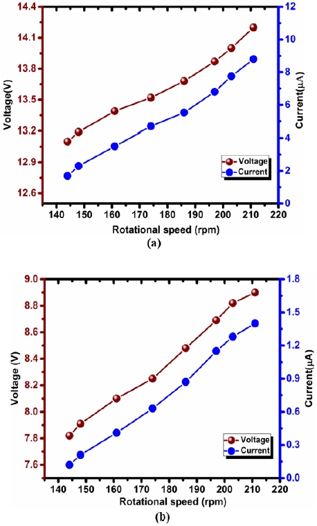
(a) Open-circuit voltage and short-circuit current of the C-TENG at different rotational speed. (b) Open-circuit voltage and short-circuit current of the D-TENG at different rotational speed
The outputs from the both triboelectric nanogenerators (C-TENG, D-TENG) were added to produce maximum efficiency, as they were connected in series. Fig. 8.(a) shows the constructed circuit with a series connection and two bridge rectifiers, which convert the alternating current (AC) into direct current (DC). Fig. 8.(b) and Fig. 8.(c) present the combined short-circuit current and open-circuit voltage from both TENGs with an excellent performance of 23 V and 10 µA, respectively. Furthermore, external resistances were also employed to evaluate the DC power output. The designed generator produces a maximum DC power output of 12.2 µW at a loading resistance of 1 MΩ as shown in Fig. 8.(d).
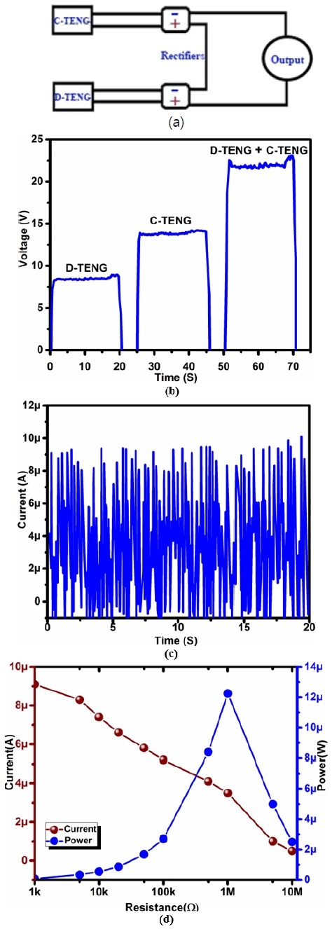
(a) Power management circuit used to combine outputs from C-TENG and D-TENG. (b) Open-circuit voltage of the hybrid generator. (c) Short-circuit current of the hybrid generator. (d) Power output of the hybrid generator
As mentioned earlier, if the scale-up of the thermomagnetic engine is done in conjunction with the operation of other types of electric generators (e.g., electromagnetic generators) along with the nanogenerators (C-TENG, D-TENG) appropriately, a considerable amount of electric power (even in kW range) can be produced from the waste heat of building HVAC systems (heat pump units).
Fig. 9. shows an up-scaled thermomagnetic engine for improving power generation and efficiency by aligning a number of thermomagnetic engines in series for multiple hot water inputs.
As most buildings use air heat pump units with air cooled condensers, some arrangements should be made to effectively recover the heat released by them. A plate type heat exchanger is one such arrangement that could be integrated with the condenser units.
For those units with water cooled condensers, the energy harvester presented in this work, could be applied without undue difficulties. This, however, has limited application as water cooled condensers are generally used for air conditioning units of large capacity in non-residential buildings.
4. Conclusions
The possibility of exploiting waste heat from building HVAC systems (<60℃) were studied in conjunction with power generation by two different types of triboelectric nanogenerators (TENGs); a cylindrical triboelectric nanogenerator (C-TENG) and a rotating disk-shaped triboelectric nanogenerator (D-TENG). A small scale thermomagnetic engine was designed, fabricated, and tested to drive TENGs which deemed quite suitable in developing power for practical applicability. The combined output of the TENGs reached an open-circuit voltage and short-circuit current of 23 V and 10 µA, respectively, for the temperature difference of 45℃. It could have generated even higher power output with a special modification of the FEP and aluminium. Also, it is worthwhile to note that the maximum power output from the proposed designed in combination with the other types of electromagnetic generator could be developed for enhanced power generation capability in harnessing low-grade thermal energy from building HVAC systems.
Acknowledgments
This research was supported by the 2019 scientific promotion program funded by Jeju National University.
References
- The Energy Flow Chart Released by Lawrence Livermore National Laboratory. Availableonline: https://flowcharts.llnl.gov/content/assets/images/charts/energy/energy_2011world.png, (accessedon21January 2018).
- N. Tesla, Thermo-Magnetic Motor, U.S. Patent, 396121, 1889.
- T. A. Edison, Pyromagnetic Motor, U.S. Patent, 380100, March 1888.
- T. A. Edison, Pyromagnetic Generator, U.S. Patent, 476983, June 1892.
- N. Tesla, Pyromagneto-Electric Generator, U.S. Patent, 428057, May 1890.
-
L. D. Kirol, J. L. Mills, Numerical analysis of thermomagnetic generators, Appl Phys, 56(3), 1984, pp.824-828.
[https://doi.org/10.1063/1.334015]

-
M. Ujihara, G. P. Carman, Thermal energy harvesting device using ferromagnetic materials, Appl Phys Lett, 91(9), 2007, 0935508.
[https://doi.org/10.1063/1.2775096]

-
D. Solomon, Improving the performance of a thermomagnetic generator by cycling the magnetic field, J Appl Phys., 63(3), 1988, pp.915-921.
[https://doi.org/10.1063/1.340033]

-
D. Solomon, Design of thermomagnetic generator, Energy Convers Manag ELSEVIER, 31(2), 1991, pp.157-173.
[https://doi.org/10.1016/0196-8904(91)90068-T]

-
V. Srivastava, Y. Song, K. Bhatti, R. James, The direct conversion of heat to electricity using multiferroic alloys, Adv Energy Mater, 1(1), 2011, pp.97-104.
[https://doi.org/10.1002/aenm.201000048]

-
Y. Takahashi, K. Yamamoto, M. Nishikawa, Fundamental performance of triple magnetic circuit type cylindrical thermomagnetic engine, Electr. Eng. Jpn, 154, 2006, pp.68-74.
[https://doi.org/10.1002/eej.20127]

-
Y. Takahashi, T. Matsuzawa, M. Nishikawa, Fundamental performance of the disc-type thermomagnetic engine, Electr. Eng. Jpn, 148, 2004, pp.26-33.
[https://doi.org/10.1002/eej.10359]

-
G. J. Van der Maas, W. J. Purvis, Curie point motor. Am. J. Phys, 24, 1956, pp.176-177.
[https://doi.org/10.1119/1.1934177]

-
K. Murakami, M. Nemoto, Some experiments and considerations on the behavior of thermomagnetic motors, IEEE Trans. Magn., 8, 1972, pp.387-389.
[https://doi.org/10.1109/TMAG.1972.1067406]

-
H. Stauss, Efficiency of thermomagnetic generator, J Appl Phys., 30(10), 1959, pp.1622-1623.
[https://doi.org/10.1063/1.1735020]

-
H. E. Nigh, S. Legvold, F. Spedding, 1963, Magnetization and electrical resistivity of gadolinium single crystals, Phys. Rev, 132, 1963, p.1092.
[https://doi.org/10.1103/PhysRev.132.1092]

-
T. Taufik, J. Thornton, D. Dolan, Piezoelectric Converter for Wind Energy Harvesting, 9th NV Information Technology - New Generations conference Las Vegas, 2012, pp.221-224.
[https://doi.org/10.1109/ITNG.2012.38]

-
X. Wang, S. Wang, Y. Yang, Z. L. Wang, Hybridized Electromagnetic-Triboelectric Nanogenerator for Scavenging Airflow Energy to Sustainably Power Temperature Sensors, ACS Nano., 9, 2015, pp.4553-4562.
[https://doi.org/10.1021/acsnano.5b01187]

-
S. L. Zhang, M. Xu, C. Zhang, Y. C. Wang, H. Zou, X. He, Z. Wang, A. L. Wang, Rationally Designed Sea Snake Structure Based Triboelectric Nanogenerators for Effectively and Efficiently Harvesting Ocean Wave Energy with Minimized Water Screening Effect, Nano Energy., 48, 2018. pp.421-429.
[https://doi.org/10.1016/j.nanoen.2018.03.062]

-
L. Pan, J. Wang, P. Wang, R. Gao, Y. C. Wang, X. Zhang, J. Zou, Z. L. Wang, Liquid-FEP-based U-Tube Triboelectric Nanogenerator for Harvesting Water-Wave Energy, Nano Res., 11, 2018, pp.4062-4073.
[https://doi.org/10.1007/s12274-018-1989-9]

-
F. Viola, P. Romano, R. Miceli, G. Acciari, Harvesting rainfall energy by means of piezoelectric transducer, International Conference on Clean Electrical Power (ICCEP), Alghero, 2013, pp.634-639.
[https://doi.org/10.1109/ICCEP.2013.6586952]

-
H. Fu, R. Xu, K. Seto, E. M. Yeatman, S. G. Kim, Energy Harvesting from Human Motion Using Footstep-Induced Airflow, J. Physics, Conf. Ser. 660, 2015, 012060.
[https://doi.org/10.1088/1742-6596/660/1/012060]

-
P. D. Mitcheson, P, Miao, B. H. Stark, E. M. Yeatman, A. S. Holmes, T. C. Green, MEMS Electrostatic Micropower Generator for Low Frequency Operation, Sens. Actuators, 115, 2004, pp.523-529.
[https://doi.org/10.1016/j.sna.2004.04.026]

