키네틱 외피 유닛 모듈의 구동방식에 따른 타공정도의 실내 균제도 효율성 검증
ⓒ 2020 KIEAE Journal
Abstract
In the preceding study on kinetic envelope, various studies were conducted to create a suitable indoor lighting environment for each space, but the study of uniform lighting environment was insufficient. In this study, the correlation between driving method and perforation degree is analyzed to verify efficiency of improvement of fungi for indoor light environment and comfort.
The opening and closing areas and angles for inflow of proper average illumination according to the driving method were derived and compared and analyzed by drawing uniformity ratio of illuminance according to other process drawings.
First, in this study, variables for driving method and other process roads were set to establish limits for performance evaluation. Second, 25% in H-flap, 100% in V-flap, 22.5 ̊ in H-fold, 45 V in V-fold, 22.5 - in H-S.fold, and 45 ̊ in V-S.fold could be derived with an indoor average illumination of 300 to 600 lx. Third, it was possible to derive a high rate of uniformity ratio of illuminance value from 150mm/200mm of perforated panels among four of the six drive methods(H-flap, H-fold, V-S.fold, and H-S.fold). And it could be drawn that the uniformity of the perforation degree according to all driving methods is not proportional. In order to increase the uniformity ratio of illuminance, apply suitable perforation panels for the driving method shall be applied, and horizontal rather than vertical ones are suitable for improving the uniformity ratio of illuminance.
Keywords:
Light environment, Kinetic envelope, Uniformity ratio of Illuminance키워드:
빛환경, 키네틱외피, 균제도1. 서론
1.1. 연구의 배경 및 목적
건물부분에서의 에너지 소비량 중 조명에너지는 약 20%~30%의 비율을 차지하고 있으며, 조명에너지의 소비량이 증가함에 따라[1] 최근에는 루버형 외피의 제어를 통한 실내 빛 유입 양 조절을 위한 다양한 연구가 진행되고 있다. 기존 키네틱 외피가 적용된 사례 및 연구에서 외피의 특성에 따라 경제성, 조형성, 친환경성, 효율성 등 여러 면에서 문제점이 나타나고 있다. 또한 다양한 형태의 광선반 및 루버가 적용된 실내 조도 성능평가에 관한 연구는 진행되고 있지만 키네틱 외피 패널의 특성을 중심으로 균제도 효율을 향상시키는 연구는 미비한 것으로 나타났다(Table 1.). 본 연구에서는 키네틱 외피가 실내 빛 환경에 영향을 미치는 특성 중 균제도 향상에 미치는 요소를 도출하여 실내 조도 제어와 동시에 균일한 조도를 유입시켜 실내 생활환경을 개선 및 향상시키고자 한다.
1.2. 연구의 방법 및 범위
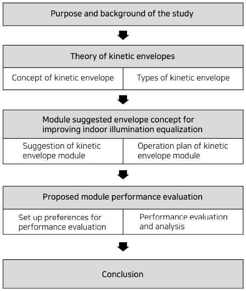
본 연구는 사례 분석을 통해 균제도 향상을 위한 변인을 도출하여 외부 환경에 따른 키네틱 외피의 변인 설정에 따른(구동방식에 따른 타공정도) 평균조도 및 실내 균제도 성능평가를 실시하여, 이후 비교분석을 통해 최적의 균일한 조도 환경이 조성되는 개폐 각도와 타공 정도를 도출하고 검증한다. 이를 위하여 본 연구는 FIg. 1.에서 나타나듯이 다음의 절차에 의거하여 진행하였다.
첫 번째, 키네틱 외피의 이론적 고찰로 개념 및 유형에 대한 고찰과 실내 적정조도 기준을 제시하기 위한 국내의 조도기준을 고찰하였다. 두 번째, 키네틱 외피 운영방식에 대한 고찰을 통해 실내 균제도 향상을 위한 방안으로 키네틱 외피의 사례 분석을 실시하여 외피에서 나타는 특성을 기반으로 2가지 변인 요소를 설정하여 변인 설정 값에 따른 균제도 성능 평가를 실시하였다.
2. 키네틱 외피 이론 고찰 및 실내 적정 조도 기준
2.1. 키네틱 외피 개념 및 유형
Farshid Moussavi는 ‘The Function of Ornament’에서 파사드를 구조, 스크린, 표면적 외피로 분류하였다. 여기서 구조란 건축물의 하중을 지지하는 역할을 하는 파사드, 스크린은 건물의 외부와 내부의 사이에 위치하는 레이어로써의 파사드, 표면적 외피는 건물의 내부와 독립적으로 분리되어 위치하며 서페이스(surface) 즉, 표면의 형태를 가지는 파사드를 의미한다[2].
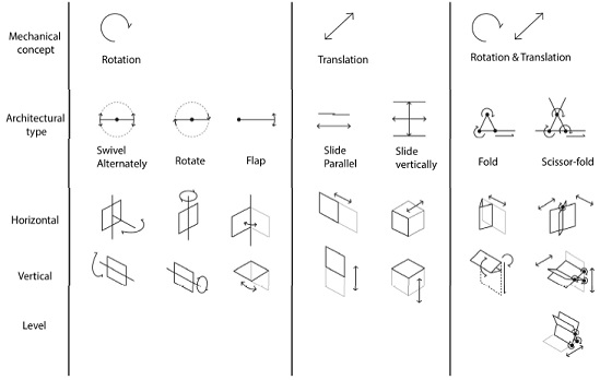
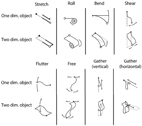
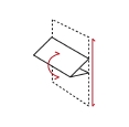
키네틱 유형은 Movement of rigid architectural elements 와 Types of the movement of deformable architectural elements로 분류할 수 있다[3]. Fig. 2. 유형은 Rotate, flap, slide, fold를 기준으로 다양하게 응용되어 구동되며 Fig. 3.은 형태의 변형이 가능하기에 Roll, Stretch 등 다양한 형태로 움직임을 나타내지만 재료의 제한이 따른다. 본 논문에서는 다양한 키네틱 유형 중 패널 형태의 외피로 적용 가능한 유형을 도출하고 기존 건축물 사례에 적용된 사례에서 제한하여 실험을 하였다.
2.2. 키네틱 외피 운영 방식
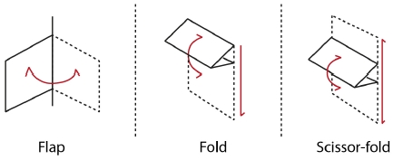
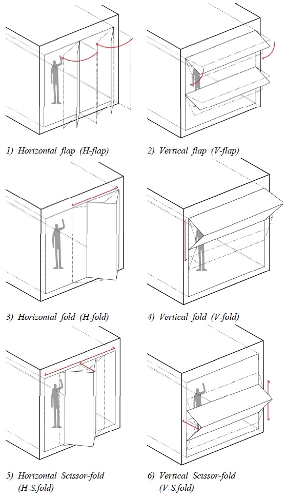
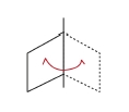
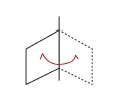
키네틱 외피의 다양한 구동 방식 중 소재의 특성에 따라 형태의 변형이 달라지는 구동방식은 비교 분석하기 어려움이 있으므로 고정된 패널 형태로 변형이 없는 재료로 제한을 두었다. 키네틱 외피는 기본 유형의 동작인 Rotation, Translation 두 가지 조합으로 구동방식이 다르게 사용된다(Fig. 2.). 1차적으로 Rotate, translation, rotate & translation으로 구분되며 2차적으로 Rotate, flap, slide, fold, scissor-fold로 구분할 수 있다[3]. 구동방식 중 Rotate와 slide는 개폐를 하는데 있어서 필요로 하는 면적이 다른 유형보다 2배 이상을 필요로 하는 것으로 판단하여 제외하고 3가지 유형으로 유형을 실험을 위한 키네틱 외피 유형으로 분류하였다(Fig. 4). 본 연구에서는 외부 환경에 따른 동일한 기준과 실험을 위한 제한으로 3가지의 유형으로 flap, fold, scissor-fold의 수직(Vertical)형, 수평(Horizontal)형으로 Fig. 2.와 같이 분류하였다.
2.3. 키네틱 외피 사례 분석
본 연구에서는 키네틱 파사드가 적용된 6가지 사례들을 통해 키네틱 외피가 실내 빛 환경에 영향을 미치는 다양한 특성을 도출하고자한다. 다양한 특성 중 키네틱 외피의 균제도 효율에 영향을 미친다고 판단되는 요소 2가지를 도출하여 여러 변인을 주고 동일한 공간규격에 적용하였을 시 성능평가를 하여 유형별 균제도 향상을 위한 개폐면적 및 각도를 파악하고자 한다.
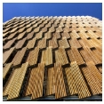
사례분석을 통해 균제도 향상에 영향을 미치는 요소로 키네틱 외피 모듈의 재료, 색상, 구동방식, 타공정도로 나타는 것을 파악할 수 있다. 위 사례(Table 2.) 6개 중 4개의 키네틱 외피에서 타공된 형태의 패널로 구성이 되어있었으며 2개의 외피 패널은 솔리드 패널로 구성 되는 것을 알 수 있다. 구동방식 중 flap은 수직(Vertical)형으로 구동되어지며 Fold와 Scissor-fold는 수평(Horizontal)형 구동방식으로 구성되어있는 것을 알 수 있다. 이러한 특성은 시쾌적성, 경량성, 경제성을 고려하였지만 채광을 완벽히 차단을 할 수 없다. 본 연구에서는 사례를 통한 외피의 특성 중 가장 큰 특징으로 나타나는 구동방식과 타공정도로 균제도에 영향을 미치는 변인 설정 요소로 한정 지었다.
3. 실내 조도 균제도 향상을 위한 모듈 제안
3.1. 키네틱 외피 운용 방안 및 모듈 제안
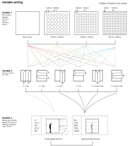
본 연구는 architecture in motion-dynamic components and elements[3]에서 나타난 키네틱 유형 중 Rotate와 slide는 개폐를 하는데 있어서 필요로 하는 면적이 다른 유형보다 2배 이상을 필요로 하는 것으로 판단하여 제외하고 사례에서 가장 많이 나타나는 유형 3가지(Flap, fold, Scissor-fold)의 구동방식을 비교분석하였다. 3가지 구동방식에 수직, 수평형으로 나누어 6개의 유형으로 설정하였고 6개의 구동방식에 4가지 유형의 타공패널을 적용하였다. 이 유형은 기존 키네틱 외피 사례 조사를 통한 대표 유형들을 응용하여 구성하였으며 각 변인마다 5 단계의 기준을 설정하고 개폐면적을 나누어 설정하였다. 키네틱 외피의 실내 빛 유입에 영향을 미치는 형태, 유형, 특성 요소를 변인으로 설정한 것에 대한 수치는 Table 4.와 같이 나타난다.
Fig. 5.와 같이 1차적으로 사례를 통한 3개 유형의 구동방식에 수직, 수평형으로 나누어 6개의 변인으로 구성하여 외부 빛 차양에 유요한 구동방식을 비교분석하기 위함이다. 2차적으로 패널의 균제도 및 실내조도 확보를 알아보기 위한 방안으로 타공률에 대한 변수를 4가지로 설정하였다. 3차적으로 키네틱 외피라는 특징으로 개폐 여부(각도 및 면적)가 각 유형마다 구동방식이 다르므로 구동박식에 의한 개폐기준을 표기하는 방법은 각도와 퍼센트로 구분 하였지만, 이는 수직, 수평면을 5단계 분할 개폐로 진행하였음에 실험 환경이 기준은 동일하다고 판단하였다.
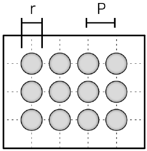
Fig. 6.은 펀칭메탈 관련 업체에서 사용되는 표준 산출 공식이다(Eq. 1). 원의 지름과 원의 중심과 중심과의 간격을 활용해서 공식을 산출하게 되며[6], 성능평가에 활용되는 타공정도의 구경은 각 150mm, 100mm, 50mm로 설정하였다.
| (Eq. 1) |
각 실험 마다 동일한 기준을 두기위해 두 개의 수직, 수평 패널을 적용하였으며 구동방식을 통한 개폐 정도를 5개 단계로 나누어 실험을 실시하였다. 한 실험체 모듈 당 한 쌍의 키네틱 외피 패널을 적용하였으며 비차폐 면적의 다른 변인을 제한하기 위함이다. 위 그림 Fig. 7.과 같이 패널의 구동 힌지는 상부 혹은 우측에 설치되어 있으며 이는 해가 동쪽에서 서쪽으로 지는 것을 기반으로 적용한 것이다.
3.2. 성능평가를 위한 환경설정
실내 빛 유입을 통한 조도 및 균제도에 대한 분석을 위한 시뮬레이션 툴로 Radiance를 사용하였다. Radiance시뮬레이션 프로그램은 lawrence berkeley national laboratory의 조명연구팀이 개발한 것으로 조도/휘도를 계산할 수 있는 시뮬레이션 프로그램이다[7]. Radiance 프로그램 툴의 타당성 검증은 박웅규 등의 연구에서 확인하였다[8]. 본 연구의 중요 변인의 외부조도는 관련연구를 근거하여 하지에 대하여 외부조도 최저값은 흐린 날의 외부조도가 5,000 lx에서 20,000 lx사이라는 내용을 근거하였다[9]. 청천공상태일 때는 직사일광이 실내로 유입되므로 채광량 면에서는 유리하지만, 직사일광의 유입으로 현휘와 조도 불균형 등으로 질적인 면에서는 불리하고 담천공 상태일 때는 양적인 면에서는 불리하나 전반적으로 고른 자연광이 유입되어, 청천공 상태일 때보다 우수한 질의 자연광 이용이 가능하여 본 연구에서는 조도의 균형된 유입을 통한 동일한 기준을 두기위해 담천공으로 한정하여 실험을 진행하였다[10]. 본 연구의 목표는 구동방식에 따른 타공정도의 균제도를 비교하여 분석하기 위함으로 한 개의 변인의 시간대별 균제도의 변화보다 다양한 변인의 균제도의 비교를 통한 효율 검증이 적합하다고 판단하여 Radiance 프로그램을 통해 국내 인천기준 하지 6월 21일 한 시간대로 날씨를 설정하여 실험에 적용하였다(Table 5.).
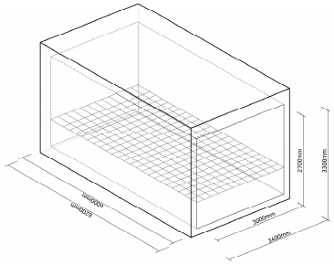
시뮬레이션 테스트를 위한 실험체 크기는 Fig. 8.에서 나타나듯이 폭 3000mm, 깊이 6000mm, 높이 2700mm의 크기이며[7], 키네틱 외피 모듈이 설치되는 창의 크기는 폭 3000mm, 높이 2700mm이다. 창의 크기는 커튼월 공법을 적용하였을 시의 전창으로 설정하였다. 키네틱 외피의 모듈 사이즈는 수평형 – 1500mm(W) ×2700 mm(H), 수직형 – 3000mm(W) × 1350mm(H) 로 유리의 외피 한 쌍을 적용하였을 시 창의 크기와 동일하게 진행하였다(Table 6.).
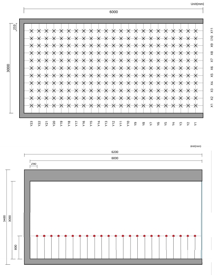
실내 조도의 측정 지점은 국내의 조도기준 KS 조도 측정기준에서 제시하고 있는 바닥면 위 80±5cm를 근거하여[11] 바닥으로부터 80cm지점에 위치시켰다. 조도 센서는 250mm 간격으로 가로 11개와 세로 23개를 배치하여 총 253개의 조도 측정 지점을 설정하였다[11](Fig. 9). 재질 값의 경우 반사값을 기준으로 window는 7.20%, facade는 10%, wall은 20%로 설정하였다(Table 7.).
3.3. 성능 평가 및 분석
본 실험은 대한민국 인천 기준 하지 6월 21일 오후 12시 한 시간대를 기준으로 24개의 변인을 두어 비교 분석하였다. 균제도의 경우 최대조도 혹은 평균조도와의 최소조도의 비로 도출하는데 본 논문에서는 평균조도와의 비로 조도값을 도출하였다(Table 8.).
Table 9.의 경우 6개의 유형 중 실내 균일한 조도 분포도를 확인하기 위한 기준으로 하지 6월 21일 오후 12시경 담천공으로 설정하여 실내 적정 조도를 확보하는 개폐면의 각도를 도출한 값이다. 6개의 유형을 분석하기 위한 기준으로 첫 번째로 조도가 (300 – 400 – 600)lx를 표현하는 각도 및 개폐면적의 정도를 분석하고, 이를 기반으로 두 번째로 동일 구동방식 중 균제도가 높은 것을 도출하였으며 세 번째로 동일 타공정도 중 균제도가 높게 나타난 것을 도출하였다. 최소조도와 최대초도를 도출한 이유는 균제도 유사시 차선으로 비교할 수 있는 요소로 최대조도가 낮거나 최소 조도가 높은 변인을 도출하기 위함이다. 다음은 균제도 효율성 검증을 위한 성능평가 비교 분석한 결과이다.
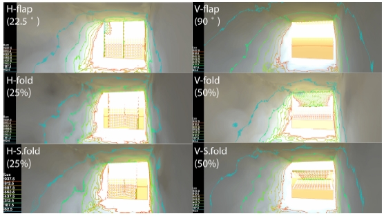
첫 번째, Fig. 10.은 150mm/200mm의 예시이며 이미지 분석을 통해 알 수 있듯이 H-flap에서는 2단계(22.5゚)에서 적정 평균조도가 나타났으며, V-flap에서는 5단계(90゚), H-fold에서는 2단계(25%), V-fold에서는 3단계(50%), H-S.fold에서는 2단계(25%), V-S. fold에서는 3단계(50%)가 5단계 중 각 구동방식 최적 개폐 각도 및 면적으로 도출되었다.
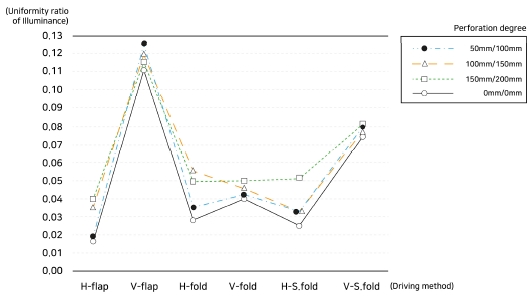
이를 기반으로 두 번째, 구동방식에 따라 균제도를 비교하였을 때 Fig. 11. V-flap 방식이 0.1 이상으로 높게 나왔으며 V-S.fold가 0.6 이상으로 높게 나온 것을 알 수 있으며 수직형보다 수평형이 균제도에 높게 나오는 것으로 나타났다. 3가지 유형의 구동방식 중 수직형, 수평형 편차가 가장 큰 것은 flap 구동방식이며 fold 구동방식은 가장 낮게 도출되었다. 이에 균제도 향상에 수직형 보다 수평형에 유리하게 나타나며, V-flap, V-S.fold 구동방식을 적용하는 것이 실내 균일한 조도 분포에 효과적이다.
세 번째, 타공정도에 따른 균제도 비교결과(Table 10.), V-flap과 H-fold를 제외한 나머지 4개의 변인 중에 150mm/200mm 타공정도가 가장 높게 나타났다. 수평형에서는 타공정도에 따른 균제도차이가 미비한 것으로 나오지만 수직형에서는 최대 0.02차이까지 나타나는 것을 파악할 수 있었다.
이와 같이 본 연구에서 키네틱 외피의 실내 균제도 확보를 위한 방안으로 6개의 구동방식 유형을 선정하여 외피의 타공정도에 의해 성능 평가를 진행한 결과 구동방식에 따른 타공정도의 균제도 효율성에 있어서 타공된 구경에 균제도가 비례하지 않다는 것을 알 수 있으며 구동방식에 따라 균제도가 향상되는 패널이 다르게 나타나는 것을 파악하였다. 구동방식마다 적합한 타공정도의 개공률을 적용하여야 균제도 향상에 있어 효율이 높아지는 것을 알 수 있다. 구동방식 마다 적정 개폐각도 및 면적을 기반으로 타공정도에 따른 균제도 비교분석을 실시하여 하였다. 6개의 구동방식 중 4개(H-flap, H-fold, V-S.fold, H-S.fold)에서 150mm/200mm가 높게 나온 것을 파악할 수 있었고 V-flap에서는 50mm/100mm, H-fold에서는 100mm/150mm이 균제도가 가장 높게 나온 것을 알 수 있었다. 균제도 효율성 면에서는 150mm/200mm의 타공패널을 사용하는 것이 용이한 것을 알 수 있었다. 150mm/200mm 타공패널을 적용하였을 시 H-fold, V-fold, H-S.fold에서는 균제도 차가 0.01의 미만으로 유사하게 나온 것으로 150mm-200mm의 타공률에서는 구동방식이 실내 균제도에 영향을 크게 미치지 않음에 외피의 다양화 및 사용자의 요구에 따라 다양한 구동박식을 적용할 수 있다.
4. 결론
본 연구는 한 시간대의 동일한 외부환경을 통해 다양한 변인의 균제도 성능 비교분석을 목표로 하였으며 균제도를 향상시킬 수 있는 요소를 도출하여 변인으로 설정하고 이를 기반으로 키네틱 외피 유닛 모듈의 구동방식에 따른 타공정도의 효율성을 검증하였다. 이에 대한 결론은 다음과 같다.
첫 번째, 6개 사례에서 나타나는 균제도에 영향을 미치는 요소와 특성을 파악하였다. 재료, 구동방식, 색상, 타공정도가 나타나며 외피 패널 특성으로는 타공이 되어 있거나 슬랫형태로 유닛모듈로 구성되어있는 큰 특징을 파악할 수 있다. 본 연구에서는 성능평가를 위한 제한을 설정하기 위해 구동방식과 타공정도로 2가지의 변인을 설정하였다.
두 번째, 6개의 구동방식과 4개의 타공정도로 총 24개의 변인을 5단계의 개폐각도 및 면적으로 나누어 성능평가를 실시하였다. H-flap에서는 25%, V-flap에서는 100%, H-fold에서는 22.5゚, V-fold에서는 45゚, H-S.fold에서는 22.5゚, V-S.fold에서는 45゚가 실내 평균조도 300~600lx로 나타나는 것을 도출할 수 있었다.
세 번째, 구동방식 마다 적정 개폐각도 및 면적을 기반으로 타공정도에 따른 균제도 비교분석을 실시하여 하였다. 6개의 구동방식 중 4개(H-flap, H-fold, V-S.fold, H-S.fold)에서 150mm/200mm가 높게 나온 것을 파악할 수 있었고 V-flap에서는 50mm/100mm, H-fold에서는 100mm/150mm이 균제도가 가장 높게 나온 것을 알 수 있었다. 균제도 효율성 면에서는 150mm/200mm의 타공패널을 사용하는 것이 용이한 것을 알 수 있었다. 그리고 모든 구동방식에서 구경률과 타공정도에 균제도가 비례하지 않는 것을 도출할 수 있었다. 균제도를 높이기 위해 구동방식에 적합한 타공정도의 패널을 적용하여야 하며 수직형보다는 수평형이 균제도 향상에는 적합한 것을 알 수 있다. H-flap에서는 150mm/200mm의 타공정도가 균제도가 가장 향상되었으며, V-flap에서는 50mm/100mm에서, H-fold는 100mm/150mm, V-fold는 150mm/200mm, H-S.fold는 150mm/200mm, V-S.fold는 150mm/200mm에서 균제도가 가장 향상된 것을 도출하였다.
본 연구는 하지 6월 21일 오후 12시 담천공 기준으로 실험 및 성능평가를 제한을 두어 실내 환경을 개선하고자 하는 것이 목표이다. 추후 연구로 본 연구를 기반으로 구동방식 대비 타공정도의 변인 중 가장 높게 나온 변인들을 변형 또는 응용하거나 타공형태에 변인을 주어 키네틱 외피 패널을 설계 및 성능평가를 실시하여 기본 구동방식과의 성능을 비교할 필요성이 있다.
References
-
최안섭, 건물의 신재생에너지 생성과 조명에너지 절약, 대한건축학회 제로에너지 친환경 건축기술 동향, 2017, pp.43-47.
A.S. Choi, Sustainable Energy Generation and Lighting Energy Saving in Buildings, Architecture, Architectural Institute of Korea Review of Architecture and Building Science, 2017, pp.43-47. - Farshid Moussavi and Michael Kubo, The Function of Ornament, New York: Actar, 2006.
-
M. Schumacher, O. Schaeffer, M. Vogt, Move: architecture in motion-dynamic components and elements, Birkhauser, Germany, 2010.
[https://doi.org/10.1515/9783034608541]

-
한국표준정보망, 조도기준, KS A 3011, 1998.
Korean Standards Service Network, Recommended levels of illumination, KS A 3011, 1998. -
김수린 외 3인, 개폐개념의 높이 조절이 가능한 광선반 성능평가, 한국: 한국생태환경건축학회 논문집, 제17권 제4호, 2017, pp83-90.
S.L. Kim et al., Research of the Development of a Height-adjustable light-shelf based on Open and Closed Concept, Korea: Journal of the Korea Institute of Ecological Architecture and Environment, Vol.17, No.4, 2017, pp.83-90. [ https://doi.org/10.12813/kieae.2017.17.3.083 ]
-
최유창, 타공반사판 적용 외부형 광선반의 조명에너지 성능평가에 관한 연구, 국민대 테크노디자인전문대학원 석사학위논문, 2016.
Y.C. Choi, Evaluation of the Application of am External Perforated Reflector on a Light-Shelf, Graduate school of Techno design, Kookmin univ., 2016. - http://radsite.lbl.gov/radiance/framed.html
-
박웅규 외 4인, Radicnace 시뮬레이션을 활용한 실내 주광조도 분포 예측식의 검증, 대한설비공학회 학술박표대회논문집, 2013, pp.694-698.
W.K. Park et al, Validation of the prediction equation for interior daylight illuminance using radiance simulation, SAREK, 2013, pp.694-698. -
이경수, 친환경 기능성 유리, 광문각, 2009.
K.S. Lee, Residental Windows, Kwangmoonkag, 2009. -
박경은, 초등학교 교실의 빛환경 평가에 관한 연구, 한국: 공주대학교 대학원 석사학위 논문, 2002.
K.U. Park, A study on the Evaluation of Luminous Environment in Elementary School Classroom, Graduate school of Kongju univ., Master’s Thesis, 2002. -
최기현, 지능형 외피 모듈 계획에 관한 기초 연구 –실내공간의 빛 환경 성능 개선을 중심으로, 국민대 테크노디자인전문대학원 석사학위 논문, 2015.
K.H. Choi, A Fundamental Study on Planning of Intelligent Skin Module - Focused on the improvement of Indoor Visual Performance, Graduate school of Techno design, Kookmin univ., 2015.

