Measurement and Verification for Energy Retrofit of an Aged Office Building : Lessons Learned and Suggestions from a Perspective of Facility Manager
ⓒ 2020 KIEAE Journal
Abstract
Concerning the scope and method of building energy retrofit, facility manager needs to consider the energy conservation measures that can enhance clients’ productivity and expand clients’ asset value as well as building energy performance and economic feasibility. However, client’s execution permission may not be easily obtained due to expensive professional energy audit. Since facility manager knows well about the building condition, if facility manager does a preliminary measurement and verification prior to professional energy audit, it would help facility manager resolve issues proactively, such that would help facility manager provide the data and reasoning to persuade owner and clients. Eventually it would lower cost and save time for professional energy audit and energy retrofit afterward.
This study identifies the current status of energy flow and use in facilities for requesting professional energy diagnostic, and lists the foundational data types and collection methods to request a diagnosis order to the owner, thereby proposes a preliminary diagnostics process, which can be conducted by the facility manager independently.
This study provides a case study for an actual aged office building to demonstrate how the advantages and disadvantages of energy conservation measures can be analyzed and selected from the facility manager’s viewpoint and how to consult and persuade the owner and derive a building management measure that can minimize future energy costs, because the facility manager determines the scope and duration of the energy diagnosis and loss costs due to reduction in the efficiency of client’s work is calculated and consulted with the owner.
Keywords:
Measurement & Verification, Energy Retrofit, Office Building, Facility Management1. Introduction
Facility management (FM) maintains the largest and most valuable assets of the organization such as real estate, buildings, equipment, and other environments that accommodate the employees, productivity, inventory, and other important elements needed for operations. Their duties involve environment management, work management, and asset management according to the scope of the task[1]. Environment management refers to comprehensive building facility management that aims to minimize discomfort caused in building environments when clients conduct works. This role is accepted in Korea as the sole scope of FM. Internationally, however, the FM is more focused on providing support to clients in achieving their tasks and comprehensive assistance to assets and finance-related activities of owners. Thus, even when an FM suggests or offers consultation on the scope or format of a building energy retrofit with an owner, they should consider not only the building energy performance improvement and economic feasibility but also the energy conservation measure (ECM), which can increase the asset value of the owner and enhance the work efficiency of clients.
The retrofit of buildings begins with a request of energy diagnosis from the FM under the current domestic context. After the request, an energy audit professional visits the site and analyzes the data collected in the building automation system (BAS) and field measurements. Then, the audit professional reports the ECM and cost to be replaced or repaired. The FM determines the replacement or repair draft considering the urgency and economic feasibility in consultation with the owner and, after issuing an order, a preferred bidder is designated to determine the final draft, cost, and schedule before the project starts[2].
However, since the energy diagnosis takes at least millions of Won, it is not easy to acquire permission for spending the diagnostic cost from the building owner without quantitative basis and proof. In addition, similar to cases involving most aging buildings in Korea, if the current status is diagnosed only with field measurements without in-house measurement data, even the diagnosis cannot start due to the expensive diagnostic cost including the measurement cost. In many cases, when aging buildings are neglected without persuasion of the owner for a long time, their systems may stop and replacement or repair may be required urgently with a much larger cost. This is likely to suspend or interrupt the work of occupants and lead to complaints and claims and-in the worst case, when neglect occurs unintentionally-the contract of facility management may be canceled on grounds of the unreliable duty performance.
Thus, a FM should actively respond to problem solving considering the possibility that the problem may not be solved with fragmentary measures once the problematic circumstances are detected, and persuade the owner to reach a reasonable decision without mending the barn after the horse is stolen.
2. Research Methods and Objectives
The study identifies the current status of energy flow and use in the test facility for requesting professional energy diagnostic, and thus lists the foundational data types and collection methods to request a diagnosis order to the owner, thereby proposes a preliminary diagnostics process, which can be conducted by the FM independently. This study follows standard Measurement and Verification (M&V) protocols[3-7], and refers to several domestic research studies[8-12] for setup M&V steps.
The study aims to present a case study for actual buildings to demonstrate how the advantages and disadvantages of ECMs can be analyzed and selected from the FM’s viewpoint and how to consult and persuade the owner and derive a building management measure that can minimize future energy costs, because the FM determines the scope and duration of the energy diagnosis and loss costs due to reduction in the efficiency of client’s work is calculated and consulted with the owner.
3. Measurement and Verification for Energy Retrofit
3.1 Description of test facility
The test building is a 32 floor office with 8 basement floors located in Seoul. Although it was built about 25 years ago, original HVAC&R systems except for boilers are servicing heating, cooling and air conditioning. It is covered with curtain walls that are assumed to be plane glazing instead of low-e glazing. Large envelope cooling and heating demands are thus expected; for example, as occupants who are seated next to the envelope keep reporting cooling dissatisfaction, Electric Heat Pumps (EHPs) are especially installed around the perimeter zones. As female occupants seating next to the envelope also keep reporting insufficient heating, individual heaters are specially permitted for them.
Also server rooms for the clients running IT business are under 24x7 cooling service, while more occupants report cooling dissatisfaction as internal heat gains keep increasing due to increasing computer, communication, and OA devices. Fortunately, building service manager does agree to expand the chilling capacity by replacing the existing chillers, but is somehow reluctant to suggest the replacement to owner due to a huge first cost. Since original BAS is not working currently, no data has been acquired except for Air Handling Unit (AHU) supply air temperature. Thus only monthly electricity and gas uses are available. Consequently, no measurable data to analyze occupants’ and clients’ complaints make professional energy audits more difficult and even more expensive.
3.2 Selection of M&V method and its procedure
M&V refers to the process of using measurements to reliably determine actual savings occurring within an individual facility [8]. The savings can be calculated by comparing the measured values between before and after. Although there are four established M&V methodologies to compare the savings[8], only the calibrated simulation method (Option D) is applicable to the test facility, because daily measurements are required for other options. The advantage of the calibrated simulation M&V is that it can achieve a detailed energy breakdown and energy flow analysis even with a small data input depending on “the fidelity of the energy model structure” when measured data are rarely available as shown in the test facility. However, it has a significant disadvantage in that it can damage “the fidelity of the energy model” itself due to the input value owing to subjective judgment of the modeler. Thus, inputs whose quantitative basis such as measurement is weak should be excluded as much as possible, and uncommon input values should be prevented. Furthermore, model calibration should be conducted while maintaining the model defaults as much as possible. Aslo once the calibration is complete, it should be verified by a third party with professional knowledge in building simulations.
The completeness of the calibrated simulation is determined by analysis of deviation of the actual electricity and gas usage from the calibrated simulation results, in which coefficient of variation root-mean-squared error (CV-RMSE) and normalized mean bias error (NMBE)[3] are used as indicators. Because only the monthly electricity and gas uses are available in the test facility, the allowable limits of NMBE and CV-RMSE were set to +-5% and +-8%, respectively, according to the International Performance Measurement and Verification Protocol (IPMVP) criteria[3].
3.3 Limitations of collecting data for calibrated simulation M&V
The data and references about building operation and characteristics of building and systems that could be collected in current time for calibrated simulation are as follows:
(1) Drawings: Some underground floor plans and reference story’s floor plans and cross-sections could be obtained, but the detailed drawings that could estimate the physical properties of facade, underground walls, and internal walls could not be obtained. The elevation was replaced with the building photo.
(2) The facility schematic diagram and equipment list: Fortunately, specifications of various facilities and measurements at the time of completion of the building were specified in the testing, adjusting and balancing (TAB) report. However, replaced or repaired equipment details and specifications of EHP, and system energy flows in underground restaurants etc., which were different from those at the time of building completion were not additionally managed. Thus, they were acquired after interviews with the building service manager.
(3) Building operation data, number of occupants, lighting, and device density: Although monthly and seasonal general building operation schedules could be obtained, the operation schedules and indoor setpoint temperatures on each floor, which were set differently by clients, could not be determined.
(4) Energy use: The monthly electricity and gas usage and electricity usage for lighting in the entire building were available, but daily usage for each device was not recorded.
3.4. Calibration process
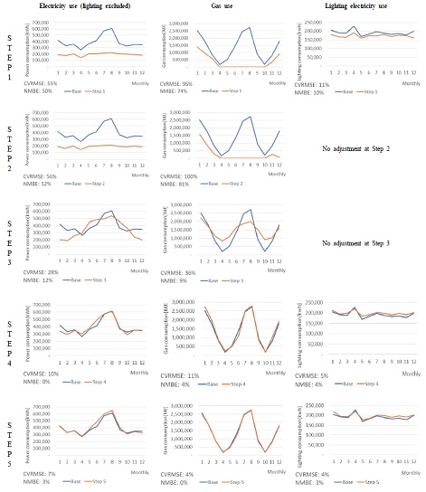
The baseline model is constructed using EnergyPlus, and it has been calibrated through five steps based on the collected data elaborated in Section 3.3.
Step 1: Base model construction
Building geometry was constructed according to the drawings and snapshots. Also HVAC&R system architecture was completed by referring TAB reports. Also energy flows between system has been updated according to system updates and supplements. All other schedules, internal heat gains, system properties are, however, kept with the EnergyPlus defaults(Fig. 1.).
Step 2: Weather data and domestic calendar update
The Seoul climate of 2018 were downloaded and formatted into the EnergyPlus weather format. And then it was included to the baseline model. Additionally, the model calendar has been updated with domestic one(Fig. 1.).
Step 3: HVAC&R system specification update
When system properties were updated per TAB reports (e.g., capacity, efficiency, performance curve, etc.), both NBME and CVRMSE have begun to decrease significantly(Fig. 1.).
Step 4: OPD, EPD, LPD and operation schedule update
To update electrical power and lighting power, number of luminaires and rated lighting power for standard floor, 1st floor lobby and basement floors have been collected. Also computers, OA equipment, and high power communication devices for the same areas have collected. Eventually average EPDs and LPDs are calculated as listed in Table 2.. Additionally, power use and lighting power for server rooms are collected. Entire OPDs are updated by referring to regular occupant number for the standard floor.
Though NMBE and CVRMSE have significantly decreased after updating the internal heat gains, weekday and weekend office LPDs during lunch time have been reduced to 30% and 10%, respectively. Office EPDs during weekday 6-8 am has been reduced to 30%, office EPDs for weekend has been reduced to 10%.
Since absorption chillers and gas boilers supply the heating and cooling, larger gas uses are observed both in summer and winter. As gas uses become smallest in April and October, the simulated gas profile mostly synchronizes with the actual when boiler efficiency is set to 45%(Fig. 1.).
Step 5: Indoor setpoint temperature update, and heating and cooling season adjustment
Although the NMBE from step 4 calibration meets the tolerance, monthly setpoint temperature is set to 25 degrees, which is based on the observation at the standard floor, in order to meet the tolerance of CVRMSE. Cooling season is set to from January to April, and heating season is set to from May to September according to the advice of building service manager. Operation hours for AHU/FCU/EHP are adjusted and pump efficiencies are set to 70%. Finally, CV-RMSE for the electric power use (except for lighting) decreases to 7%, and that for the gas use decreases to 4%(Fig. 1.).
4. Analysis of the Calibrated Baseline
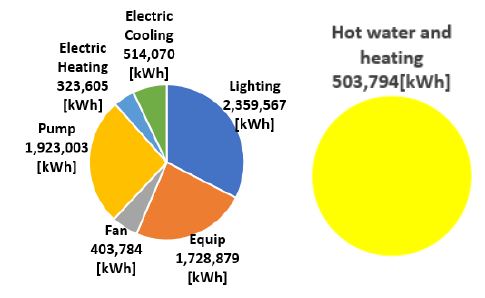
The analysis results of monthly electricity and gas breakdown in the target building after the final calibration showed that around 33% of the total electricity usage was spent in lighting and around 26% on providing electric power for cold and hot water and the operation of cooling and hot water pump(Fig. 2.). In particular, the electricity usage by fans and the pump and gas usage by boiler and absorption chillers was more in the periods of cooling and heating times from two to three up to 10 times than that in the intermediate period. Thus, it was urgent that the plant load and circulation load in the test facility be reduced above all. In addition, the heat and cooling demand was excessively increased by the heat acquisition and heat loss through the facade. Thus, it is necessary to have an ECM for the reduction of the facade load. Further details can be found in[13].
5. Proposals of ECMs and their evaluations
5.1 Building envelope and luminaire ECMs
ECM1: The building is composed of double-glazed curtain walls. Hence, the existing conditions (glass 6mm + air 12mm + glass 6mm) could be changed to low E glass 6mm + argon 12mm + low E glass 6mm to reduce the envelope load. After this change, the U-value and SHGC decreased to 1.416 W/m2K and 0.36, respectively.
ECM2: The target building is equipped with fluorescent lamps, so the lighting density is approximately 20W/m2. However, if they are replaced with LED lamps, this could be reduced to approximately 7.5W/m2.
ECM3: Daylight control for dimming artificial lighting step by step to natural light illumination in addition to LED replacement could reduce the lighting time and heat generation.
5.2 Building system ECMs
Currently, chilled water is supplied to the AHU and FCU from absorption chillers on each floor and hot water is supplied to absorption chillers, AHU, and FCU from a gas boiler. According to the building service manager, the absorption chillers installed at the time of construction are still in operation, but the boiler has been replaced once. However, the boiler efficiency was estimated to be quite low after calibrated simulation. Furthermore, because the air conditioning and heating are insufficient, the clients have installed separate EHPs and even use personal heating devices in winter. Hence, the replacement of the heat source equipment and air-conditioning equipment should be considered first. In addition, since the EHPs that have been already installed cannot be removed, the EHPs should be stopped during the winter; instead, sufficient heating should be supplied by the FCU or AHU.
ECM4: Only boilers are replaced with new condensing boilers with the same capacity and 95% efficiency.
ECM5: Heating and hot water boilers are installed separately, and cooling towers and absorption chillers are replaced with centrifugal chillers. AHUs and FCUs are not replaced, but the chilled water/hot water/cooling water pumps are replaced and a service hot water pump is added.
ECM6-16: The AHU or FCU in the ECM5 is replaced, and all cases of winter season off are considered. However, this is also linked to the EHP operation(Table 3.).
5.3 Analysis and Selection of ECMs
Because a passive ECM such as ECM1 finds it difficult to verify energy usage reduction if the system is not changed, the energy demand was compared instead. The baseline demand was 148.2 kWh/m2, which was reduced to 142.8 kWh/m2 after applying ECM1.
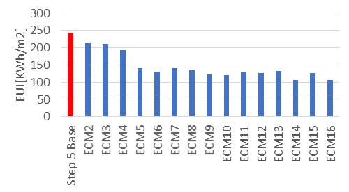
When comparing the energy use intensity (EUI) in ECM2-16, i) when replacing with LED and applying daylighting control, the energy saving was the largest (ECM3), and ii) when replacing the plant systems and AHU only and FCU winter off case (ECM14) and when replacing all plant systems, AHUs, and FCUs and FCU winter off case (ECM16), the EUI decreased down to around 106-107 kWh/m2, which showed the largest energy savings among the system changes(Fig. 3.). One thing that was noted here was that after applying ECM14 and ECM16, there was little significant difference in the EUI. This meant that even if the FCUs were replaced, but the FCUs were not used in the heating season, heating only by the brand-new AHU was the most advantageous in saving energy.
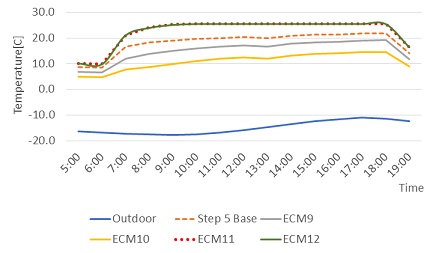
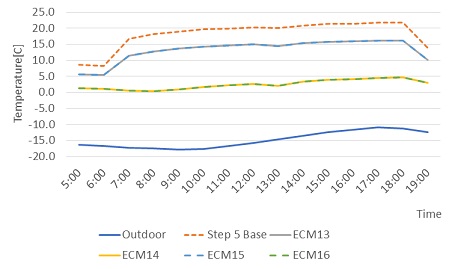
However, when comparing the room temperature during FCU winter off and the room temperature during AHU winter off in January 26 in 2018, which was the coldest day in 2018, any ECM did not attain an indoor temperature of 20 °C in the case of FCU winter off, but the AHU winter off case generally satisfied 20°C of indoor temperature during the normal working hours except for the case of only AHU replacement without changing the existing FCUs(Fig. 4. and 5.). Thus, heating only by the (brand new or existing) FCUs was considered to lead to the least possible number of clients’ comfort complaints.
6. Discussion and Conclusion
The energy saving is important from the FM’s viewpoint, but the actual operation environments (human resource management, finance management, and work environment management) in the building are also important. Thus, preliminary M&V results were discussed as follows by referring to the FM’s perspectives[2].
6.1 Energy Retrofit
(1) Changes in curtain wall: Although the U-value and SHGC of the curtain wall were considerably reduced, the energy demand per unit area and cooling and heating load were not reduced significantly as expected. Furthermore, since curtain walls were difficult to be replaced within a short period of time and curtain walls in three to four floors had to be replaced at once, the risk of occupant vacancy was large, and only curtain walls in some story could not be replaced whenever occupant vacancy occurred. Thus, it was the ECM that was considered as a last candidate.
(2) Changes in lighting equipment and control: A considerable amount of energy saving could be achieved by replacement with LED lights because the lighting density could be reduced significantly and lighting time could also be reduced using daylight control. In particular, the LED light replacement did not have a significant impact on the time and work environment operation, which was a consideration that could be reasonably proposed. For example, some locations could be replaced in consultation with an office manager in each floor even in the building operation time, and could be more reasonably achieved after working hours. Sensor installation or automatic control for daylight control could also be achieved intermittently after working hours, which did not significantly interrupt the occupant work.
(3) Replacement of plant and air-conditioning systems: The largest energy saving was obtained when replacing the plant system, AHUs, and FCUs at once such as ECM4 and ECM5. If the plant system is to be replaced, chillers should be replaced first during the heating season.
(4) AHU and FCU winter off: In case of replacing AHUs and FCU winter off, the energy saving was the most advantageous, but the indoor temperature was not sufficient to service heating only with AHUs without FCUs due to the heat loss through the facade. In conclusion, satisfiable energy savings would be achieved only with ECM9 (replacing boilers and chillers, keeping existing FCUs and AHUs, and both EHP and AHU winter off). For some occupants who claimed the comfort issue, satisfiable thermal comfort was likely to be achieved if a personal electric heater was allowed. However, when attempting AHU and EHP winter off without changing plant systems, serious comfort issues may occur, which clients should be warned about.
If air-conditioning system is replaced after replacing the plant systems, FCUs should be replaced first. That is because when replacing AHU first, the existing FCU’s capacity is designed to be less than the energy demand. Thus it is expected not to meet the indoor temperature setpoint.
(5) In addition, the replacement with high-efficiency transformer and motor, and installation of standby power saving outlets would increase energy savings In particular, replacement with these electric installations would not give a significant power load to the building operation environment, which can be a qualified candidate of considerable ECMs.
6.2 Data Collection for Diagnostics
This study estimated cooling and heating, circulating, and air-conditioning energy breakdown using the calibrated simulation; it required data about cooling and heating plant systems at least to analyze more accurately. In particular, even if a boiler was replaced, the calibrated simulation M&V shows a considerably degraded efficiency. Thus, diagnosis must be undertaken by measuring data for efficiency calculation. For the test facility, because BAS was already installed, energy use by chiller and boiler could be traceable immediately, BAS measurement function should be repaired first rather than installing ECMs.
6.3 Preliminary M&V
Because the test facility had no measurement data with sufficient resolution to start precise diagnosis, it was difficult to reach a decision on energy retrofit from the objective standpoint. Although there were the opinions of the building service manager and some clues, quantitative and objective analysis results about which systems should be replaced or repaired to some extent were not available. Thus, data collection and energy diagnosis should be conducted first, and the cost occurred, which required the persuasion of the owner. However, since the owner will not agree instantly due to the high diagnosis cost, an FM should assist the owner to make a reasonable decision.
This study derived an energy breakdown using the calibrated simulation M&V by utilizing the acquirable monthly electricity and gas uses as of the current time as much as possible, and conducted virtual diagnostics. It is true that the present study results are limited as "virtual", but they were sufficient to provide a reasonable basis of decision making to determine the energy flows and bottlenecks of the test facility and which data should be measured first and which device and facility should be diagnosed first for the owner in terms of energy wise.
The M&V from the FM viewpoint cannot simply prioritize energy saving, and can be possible only within the scope that does not affect the current building status and operating environment. Nonetheless, the FM should perform project management to enable the energy retrofit progress at a level that provides a basis and data, which can persuade the owner and client reasonably if the ECM is required mandatorily. Also the FM should make decisions to improve the asset value as much as possible while not significantly degrading the work productivity of clients and occupants.
Acknowledgments
This study was supported by the Research Program funded by the Seoul National University of Science and Technology.
References
-
M.. Potkany, M. Vetrakova, M. Babiakova, Facility Management and Its Importance in the Analysis of Building Life Cycle, Procedia Economics and Finance, 26, 202-208, 10, 1016/S2212-5671(15) 00814-X, 2015, p.2.
[https://doi.org/10.1016/S2212-5671(15)00814-X]

- UNEP Sustainable Building and Climate Initiative, Energy Efficiency in Buildings. Guidance for Facilities Managers, 2009, pp.2-15.
- International Performance Measurement & Verification Protocol Technical Committee, International Performance Measurement & Verification Protocol Volume I: Concepts and Options for Determining Energy Savings, DOE/GO-102002-1554, 2002, p.71.
- FEMP. (2008). M&V Guidelines: Measurement and Verification for Federal Energy Projects Version 3.0. Technical report, U.S. Department of Energy Federal Energy Management Program, M&V Guideline.
- IPMVP. (2010). International Performance Measurement and Verification Protocol: Concepts and Options for Determining Energy and Water Savings, Vol.1, Technical Report, Efficiency Valuation Organization.
- ASHRAE. (2002). ASHRAE Guideline 14: Measurement of Energy and Demand Savings, American Society of Heating, Refrigerating, and Air-Conditioning Engineers, Inc., Atlanta, GA.
- 2019, Guidebook for Energy Efficiency Evaluation, Measurement, and Verification, U.S. Environmental Protection Agency.
- Energy Agency, M&V Guideline about about equipment replacement, etc, The Republic of Korea: Energy Agency, 2015, pp.2-17.
- J. H. Heo, Measurement and verification for calculating energy savings, Magazine of the SAREK, 42(9), 2013, pp.30-39.
-
Y. R. Yoon, M. H. Lee, H. J. Moon, Comparison of Building Energy Prediction Models based on Machine Learning Algorithms for Hourly M&V Baseline, Journal of The Korean Society of Living Environmental System, Vol.25, No.5, 2018, pp.595-602.
[https://doi.org/10.21086/ksles.2018.10.25.5.595]

- Song S., Kim S., 2015, Development of Measurement & Verification and Commissioning Technologies for Existing Buildings(Ⅲ), Korea Institute of Civil Engineering and Building Technology.
-
J. Cho and B. Park, A Study on Dedicated Energy Baseline, Performance Options on Measurement and Verification(M&V) for Data Center Energy Saving, Korean Journal of Air-Conditioning and Refrigeration Engineering, Vol.31, No.12, 2019, pp.576-588.
[https://doi.org/10.6110/KJACR.2019.31.12.576]

- K. H. Cho, Measurement and Verification for the Improvement of Energy Performance in Deteriorated Office Buildings (M&V), Graduate School of Housing and City Seoul National University of Science and Technology, 2020, Master’s thesis.

