Analysis on the Application of Envelope Systems Developed for Apartments by Using Mock-Up Test and Simulation Tools
ⓒCopyright Korea Institute of Ecological Architecture and Environment
Abstract
An envelope system for a flexible plan, easy maintenance and reduction of construction duration of apartments was developed. External insulations that minimize the thermal bridge and components for design standards were considered and developed in this system to supply long-life housings effectively.
Materials, components and construction methods of this system were introduced. The methodology of this study was to conduct the mock-up test to confirm the performance of thermal cycling, pre-load, air-leakage, water penetration, structural performance, story displacement, and residual strain. Heating and cooling load of the house applied to the envelope system were analyzed by using EnergyPlus. The possible occurrence of condensation was analyzed by using THERM.
In the mock-up test result, the performance of all tests were satisfied by the standard of ASTM and AAMA and it would be possible to apply to real residential buildings. In the energy results, heating load of the house applied the envelope systems was lower 2.6% than that of the existing house. And the cooling load of the house was 0.4% higher. For future research, further test for fire and noise would be needed.
Keywords:
Envelope System, Long-life Housing, Performance1. Introduction
1.1. Background and purpose
Apartments with shear wall system puts economy first so that they are constructed with concrete structural walls which play two roles to support building structural load and divide rooms. Although external walls do not support load, they are constructed as concrete walls in the same as structural walls. As a result, the internal space of apartments is fixed and is limited in responding to a variety of life styles and needs of residents [1, 2]. In addition, since it is hard to check and repair apartments in the aspect of maintenance, apartments simply aged 30 years come to be re-constructed [3, 4]. On contrary, in office buildings, their columns support the buildings and interior walls play a role as a partition of internal space. An envelope called 'curtain wall' is a non-structural wall playing a role as a 'curtain' to separate the external space from the internal space [5]. These external and internal walls are made in factories and then are installed in a site. They can be replaced when old or necessary.
With rises in single-person households and the aged population, there are more demands of spatial plans for responding to the demographic change and more residents' needs for a variety of family types and residential types. In this aspect, housing-space flexibility and acceptability are required, which are the ways of using long-life housing [6,7]. By replacing variable components like interior materials, except for structures supporting load, it is possible to respond to the demands of residential space flexibly, to maintain buildings easily, and lengthen the lifespan of a building. In order to respond to housing flexibility effectively and to secure easy repair of an old building, it is absolutely necessary to systemize building materials as flexible components and thereby to make them interactive [8].
The purpose of this study is to scrutinize if the envelope system developed to lengthen the lifespan of an apartment is applicable as an external wall through Mock-Up test. In addition, in simulation, it is aimed at examining and analyzing condensation prevention performance and energy performance of the envelope system in terms of thermal environment.
1.2. Methodology and scope
The developed envelope system are comprised of standardized units which can be replaced easily and be attached and detached. For convenient construction, as an integrated type with insulation, it was developed as external insulation. In order to apply the developed envelope system to one household in an empirical apartment complex constructed in 2017, it was analyzed the structural performance and environmental performance for an external wall of an apartment through Mock-Up test.
A specimen was made in the same size as the external wall of the living room in an apartment. As for structural performance, wind load test was conducted to measure residual strain and relative story displacement. As for environmental performance, water penetration performance test, thermal cycling test, and air leakage performance were conducted. Also, the apartment with the developed envelope system was compared with conventional concrete external wall as energy performance. In order to find a difference in cooling and heating performance of housing, the dynamic simulation program 'EnergyPlus' was used. Also, in order to analyze whether condensation occurs in the condition of design code for condensation prevention, the thermal-analysis program 'THERM' was used.
2. Introduction to the Developed Envelope System
2.1. Overview and components
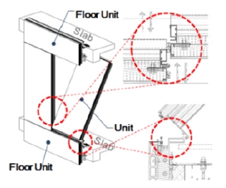
Conventional envelopes of apartments are concrete walls and doors & windows. The external walls excepted side ones are not structural ones, but are constructed at the time of concrete casting for easy construction, water penetration and air leakage. The envelope system in this study is comprised of Floor Unit and Unit as shown in Fig. 1. The Floor Units are installed in upper slab and lower slab, and Units are installed in each floor in the vertical direction. A Floor Unit frame is installed in the retractible fix type so as to secure constructability and installation stability. A Unit can be assembled in the indoor side of each floor in tilt-in way, and can be attached and detached easily if necessary. The envelope system is produced in a factory and is assembled in a site, and features attachability & detachability for easy construction. From the perspective of long life, it has a standardized unit model form that makes it possible to respond to building deterioration for replacement, and to accept a variety of flexibility.
A Floor Unit is an external-insulation integrated system comprised of ECP, 100mm of insulation, an aluminum frame, an additional insulation and a CRC board. A Unit has a CRC board installed in its external side and the same material as the floor unit in its inner side (Table 1).
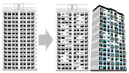
If this attachable & detachable envelope system is applied to an apartment, it is possible to respond to building deterioration and spatial flexibility. If attachable & detachable wall systems are applied to inner and external walls of an apartment, residents are able to change the internal space depending on their life style. In other words, it is possible to change the space of kitchen and bathroom to a room or other forms. Fig. 2 illustrates the changing facade along with interior design plan of each household using the developed envelope systems.
2.2. Construction consideration & improvements
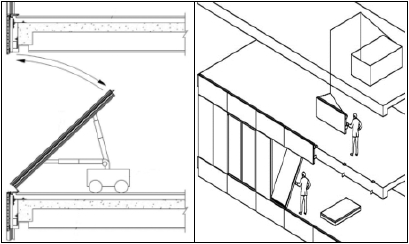
To install, disassemble, and transport the envelope systems, indoor small equipment is taken into account as shown in Fig. 3. For construction precision in a site, a fixture frame was taken into consideration until Floor Units were fixed and then Units were installed. The detachable & attachable envelope system is a modular unit so that it can be easily constructed in a site.
The joint of a Floor Unit and a Unit is connected with a hinge for rotation. So tilt-in type was applied for each attachment & detachment. A Floor Unit and a slab were fixed with an anchor.
Because it is used as an external wall, it is important for the joint of each unit to secure air leakage and water penetration performance [9].
In case of conventional wall construction in an apartment, an insulation is installed after the process of concrete casting and curing. Compared to the construction period of the conventional method, the developed envelope system has no curing and additional insulation construction periods so that it is possible to shorten a construction period. In case of external insulation construction, in order to install an insulation after frame construction, a scaffold and a gondola are installed. For this reason, the issues of constructability, safety, and delayed construction time and construction cost increases. However, the envelope system developed in this study can address the issues, for it can be installed indoor.
3. Performance Measurement
3.1. Overview and test
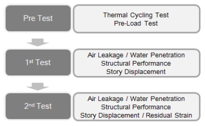
The developed envelope system was analyzed through the Mock-Up test process as shown in Fig. 4. The test process has three steps. As pre-test, Thermal Cycling Test and Pre-Load Test were conducted. Air leakage, water penetration, structural performance, and story displacement were measured as the second test. After that, residual strain was tested. According to ASTM and AAMA standards for the performance of external walls or curtain walls, the envelope system was applied to Mock-Up test.
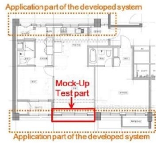
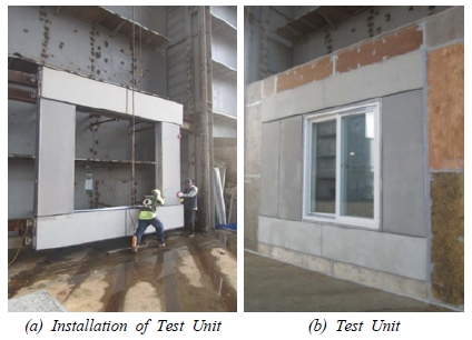
The size of the test specimen was the same as the size of a living room in an empirical apartment complex to which the developed system would be applied. The part to which the developed envelope system is applied is the external wall of the front and rear parts in the plan of Fig. 5. In order for the Mock-UP test with the components described in chapter 2, they were installed as shown in Fig. 6. The overall test figure is presented in Fig.7. The specimen has 4.1m(W) × 3.4m(H) in size, and the PVC window installed in the center has 1.8m(W) × 2.1m(H) in size. The external glass has 22mm(5mm Clear+12mm Air+5mm Clear), and the internal glass has 22mm, equally.
After an chamber was installed separately in the outside of the specimen, heating was operated to the chamber with 24℃ at 82℃ for one hour, according to the temperature condition of AAMA 501.5.After the temperature was kept at 82℃ for two hours, it slowly lowered to –18℃ for 2 hours, and was kept for 2 hours. After that, the temperature increased to 24℃ for one hour. This 8-hour cycle was repeated three times in 24 hours. In this case, the indoor temperature was kept at 24℃±3℃, and liquid nitrogen was used to lower a temperature. After thermal cycling test, air leakage performance test and water penetration performance test were conducted so as to evaluate thermal performance of the specimen indirectly.
If wind load of the specimen is positive pressure, it is 124.7kgf/㎡ equivalent to the wind speed of 44.7m/s. If it is negative pressure, the wind load is 236.7kgf/㎡ equivalent to the wind speed of 61.5 m/s.
The pre-load test is conducted in the way of imposing 62.4kgf/㎡, 50% of positive pressure and keeping it for 10 seconds. The purpose of the test is to determine whether performance test can continue to be conducted after pressure is removed and abnormality is examined.
This test is conducted in the way of keeping the pressure of +7.6kgf/㎡, test standard pressure, and measuring air leakage from the specimen. In this case, the test is conducted until the test standard pressure remains stable. In consideration of the air infiltration rate of the chamber, it should be converted to a standard air infiltration rate.
This test is conducted in the way of keeping 30.4kgf/㎡ of positive pressure and spraying 204L/㎡ for 15 minutes, and measuring water penetration.
In dynamic pressure, water penetration is tested. In this case, it is necessary to blow the wind equivalent to 30.4kgf/㎡ with the use of an aircraft engine in order to check water penetration.
This test is conducted in the way of remaining 50% and 100% of the designed wind pressure of the specimen for 10 seconds, and measuring the max displacement of some points of the unit panel and the window part.
This test is conducted in the way of imposing the displacement of 9.4mm(L/300) left and right, each, horizontally and examining if the functions and appearances of all parts have problems. The allowable criteria are applied differently depending on each of three groups: essential facility group including hospital and school, high occupancy assembly group including apartment and multi-use facility, and general building group. In the Mock-Up test, the criteria of densely populated building group were applied.
This test is conducted in the way of keeping the positive pressure (75%) and negative pressure (150%) of the designed wind load of the specimen for 10 seconds and then removing the pressure, and measuring the residual strain of each part.
3.2. Test results
The performance results of Mock-Up test are presented in Table 2.
According to the thermal cycling test and pre-load test, no abnormality was found. In the way of opening, closing, and locking the window at least five times, any abnormality was checked additionally.
The value of air leakage performance test was 1.09CMH/㎡ in a fixed unit. The 1st test resulted in 1.07CMH/㎡ and the 2nd test had 1.05CMH/㎡, both of which met the criterion. In the 1st and 2nd tests of static pressure and dynamic pressure based air leakage performance, no leakage was observed so that the standard was satisfied.
The criteria of structural performance test are less than 12.43mm of displacement in the vertical direction, and less than 23.22mm of displacement in the horizontal direction. In the test, 1.53mm of vertical displacement and 0.71mm of horizontal displacement were measured at positive pressure; 11.21mm of vertical displacement and 1.14mm of horizontal displacement were measured at negative pressure. Therefore, the specimen including glass met the standard.
Regarding the allowed values in the residual strain test, a vertical member has less than 4.35mm, and a horizontal member has less than 8.13m. In the test, the displacement of a vertical member was 1.3mm and the displacement of a horizontal member had 0.2mm. In terms of wall deformation, the specimen was found to be safe. Therefore, the system was satisfied in the structural and environmental performance tests to apply external walls, so that it came to be applicable as an external wall of an apartment.
4. Energy Performance and Condensation Occurrence
4.1. Model
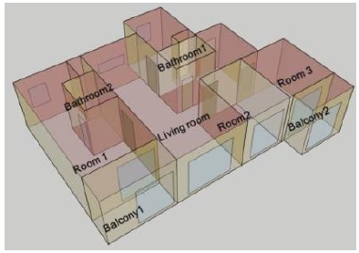
One household in the empirical apartment complex to which the envelope system would be applied was selected as the target subject to evaluate. The household is located in the center of the middle floors so that its front and back sides are exposed to the outdoor. It has 59㎡ in size, and three rooms, two bathrooms, one living room, and kitchen. Fig. 8 illustrates the sketch-up modeling for energy analysis. Based on the design code of apartment condensation prevention (Ministry of Land, Infrastructure, and Transport Notification No. 2016-835, 2016.12), the performance of condensation prevention of the parts to which the envelope system was applied was examined.
With the EnergyPlus developed by the US DOE(Department of Energy), heating and cooling load of the household was analyzed. The conventional wall to compare with has 200mm of concrete, 120mm of internal insulation, and 0.21W/㎡K of thermal transmittance according to Energy Performance Index Code(EPI Code, Ministry of Land, Infrastructure, and Transport Notification No. 2017-71). The window as double glazing sizes 22mm, and its thermal transmittance is 1.2W/㎡K. The features of the window are equal to those of the window in the household with the envelope system, and the thickness of an insulation is also the same. However, the envelope system has air space after the installation of the 100mm insulation, and has the 20mm insulation additionally.
The developed envelope system has air space internally. In case of a factory airtight product that exceeds 2cm according to EPI Code, the thermal resistance of air space is 0.17㎡K/W. For this reason, the value was applied in the energy simulation.
For input data, infiltration rate was 0.2 time/h, ventilation rate was 0.5 time/h (Regulations of Building Facility Standards, Etc., 2013). For the input values of internal heat gains (people, lighting, and miscellaneous), ASHRAE code was referred to. Setpoint temperture for heating was 20℃,and cooling temperature to 2 8℃. Roof and floor were supposed to have no heat transfer, and bathroom, balcony space, and shaft space were set as unconditioned space for analysis. Detailed input conditions are presented in Table 3.
For weather data, the Seoul weather data offered by EnergyPlus was used. In order to observe heating and cooling load, Idealload of the program was executed.
4.2. Results of energy performance
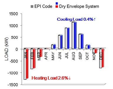
With the conventional internal insulation wall with thermal transmittance of EPI Code and the household with the developed envelope system for evaluation, monthly heating load and cooling load were analyzed as shown in Fig. 9. Up to now, heating energy of apartment only was researched, but this study looked into monthly cooling & heating load. It is important to find energy saving factors by analyzing heating and cooling load of apartment.
The annual heating load of the conventional system based apartment was 2,993kW, and that of the apartment with the developed envelope system was 2,915kW, about 2.6% lower heating load. On contrary, the annual cooling load of the conventional system based apartment was 2,120kW, whereas that of the apartment with the developed envelope system was 2,130kW, about 0.4% or 10kW higher. The annual cooling load was more than 2,000kW which was more than 65% of the annual heating load.
In the condition where the insulation thickness, the thermal transmittance, and internal heat gains were equal, the envelope system including air space had 2.6% lower heating load, and 0.4% cooling load higher. Air space was created in the envelope system so that heating energy was saved. However, cooling energy in summer was found to be a little high.
4.3. Results of condensation occurrence
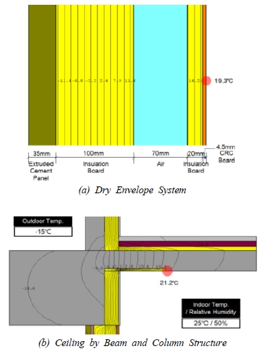
According to the design code for apartment condensation prevention, in the condition where the region to which the envelope system is applied is region Ⅱ, outdoor temperature is – 15℃, indoor temperature is 25℃, and indoor relative humidity is 50%, thermal analysis was conducted. The results are presented in Fig. 10. In the indoor condition, dew point temperature was about 13.9℃. As the result of THERM simulation, the surface temperature of indoor wall was 19.3℃. TDR(Temperature Difference Ratio) was calculated to 0.143.
The empirical complex to which the envelope system is expected to be applied has frame structure, and the envelope system is installed under a beam. In the slab connected to the beam, internal insulation and ceiling condensation prevention insulation are installed. For this reason, the ceiling condensation occurrence was predicted. When the insulation with 15mm in thickness and 450mm in length was applied to ceiling, its surface temperature was 21.2℃, higher than dew point temperature.
5. Conclusion
The envelope system attachable and detachable for flexible plan and easy maintenance was developed. Its structural performance and environmental performance were examined through Mock-Up test and simulation. In this way, its energy performance and condensation occurrence were also analyzed. The results of this study are summarized as follows.
First, the envelope system developed as a building technology of long-life housing can be made in factory and installed indoor, featuring easy construction and a short construction period. The units of the envelope are based on flexible module type so that it is possible to give diversity and functionality to building facade.
Secondly, in order to examine the performance of the developed system, a mock-up model was created. With the specimen, thermal cycling test, pre-load test, air leakage performance, water penetration performance, structural performance, story displacement, and residual strain test were conducted. According to these tests, the envelope system was satisfied the criteria of ASTM and AAMA so that it secured structural performance and environmental performance. Therefore, it is possible to apply the envelope system to an external wall.
Thirdly, the heating load of the apartment with the developed system was about 2.6% lower than that with the conventional wall system that follows EPI Code, but its cooling load was 0.4% higher. Air space was created in the envelope system so that heating energy was saved but cooling energy in summer was a little high.
Fourthly, in the same condition as the design code for apartment condensation prevention, the temperature distribution of the parts where condensation was predicted to occur on the envelope system and the empirical apartment complex was examined. The indoor surface temperature of the envelope system was 19.2℃ and the surface temperature of ceiling was more than 21.2℃. Therefore, they were analyzed to be higher than dew point temperature as 13.9℃.
To apply the envelope system to an apartment, it will be necessary to test for fire resistance performance and noise.
Acknowledgments
This study was made possible by financial support from part of results a major research project conducted by the Korea Ministry of Land, Infrastructure and Transport, Residential Environment Research Project in 2017. (Project No.: 17RERP-B082173-04)
References
-
모정현, 이연숙, 지속가능한 주거 개발을 위한 가변성 개념의 유형학적 분석, 한국생태환경건축학회 논문, 3(3호), (2003), p59-66.
Mo Jeong-hyun, Lee Yeun-sook, Typological Analysis of the Flexibility Concept for Sustainable Housing, Journal of KIEAE, 3(3), (2003), p59-66. -
박준영, 외3인 , 2000년대 한국 아파트 단위세대의 공간구성 동향 변화, 한국생태환경건축학회 논문, 제12권(제1호), (2012), p21-27.
Joon Young Park, Sang Kyu Jeong, So Yi Cheong, Woo Jang Park, Trend Changes of Spatial Configuration in Housing Units of Korean Apartments in the 2000s, Journal of KIEAE, 12(1), (2012), p21-27. -
이정석, 외3인 , 차세대 장수명 공동주택의 가변성능 향상을 위한 건축요소기술 우선순위 결정에 관한 연구, 한국건설관리학회 논문, 제10권(제2호), (2009), p84-92.
Jeong-Seok Lee, Gun-Hee Cho, Jeong-Rak Sohn, Je-Jun Kim, Selection on the Order of Priority Factor of Construction Key Technology for Improving the Flexibility for a Long Life Apartment Housing at the Next Generation, Korea Journal of Construction Engineering and Management, 10(20), (2009), p84-92. -
김세환, 외2인 , 공동주택 관련 법규 및 인증제도에 대응가능한 설비요소기술 및 시스템에 관한 연구, 한국건축친환경설비학회논문, 제5권(제4호), (2011), p265-272.
Se-Hwan Kim, Kyung-Soon Park, A Study on Elemental Technology and System that is respond to the Laws and Certification System associated with the Long-life Housing, Journal of KIAEBS, 5(4), (2011), p265-272. -
정을규, 임칠순, Curtain Wall 특성 및 설계조건에 관한 연구, 한국건축시공학회 논문집, 4(3), (2004), p125-131.
Eul-kyu Jung, Chil-Soon Lim, A study on the characteristic and designing condition of Curtain Wall, Journal of KIC, 4(3), (2004), p125-131. [ https://doi.org/10.5345/JKIC.2004.4.3.125 ]
-
조일아, 김형우, 공동주택 단위세대의 가변형 평면 유형 분류에 관한 연구, 대한건축학회 논문, 제22권(제12호), (2006), p67-74.
II-A Cho, Hyung-Woo Kim, A Study on Classification of a Flexible Unit-Type in Apartment Unit Plan, Journal of AIK, 22(12), (2006), p67-74. -
강지연, 김형근, 장수명주택 보급모델의 가변성능 확보를 위한 계획요소 도출, 대한건축학회 학술발표 논문, 제37권(제1호), (2017), p109-110.
Ji-Yeon Kang, Hyung-Geun Kim, A Study on the Planning Requirements for Flexibility in the Prototype of Long-Life Housing, Conference Journal of AIK, 37(1), (2017), p109-110. -
권나영, 외4인 , 공동주택에 있어서 가변형 평면계획의 특성에 관한 연구, 대한건축학회 학술발표 논문, 제27권(제1호), (2007), p315-318.
Na-Young Kwon, Su-Yong Jin, Seung-Hee Lee, Leem-Jong Jang, Sang-Ho Yi, A Study on the Characteristics of Flexible Unit Plan of Apartment, Conference Journal of AIK, 27(1), (2007), p315-318. -
박선효, LCCO2 분석에 의한 건식 외피 시스템 평가, 대한건축학회 논문, 제29권(제1호), (2013), p229-237.
Sun-Hyo Park, The Evaluation of Apartment Envelope System by LCCO2 Analysis, Journal of AIK, 29(1), (2017), p229-237. [ https://doi.org/10.5659/JAIK_PD.2013.29.1.229 ]
-
Goopyo Hong, Hye Jin Kim, and Byungseon Sean Kim, Design Proposal for Low Energy Buildings using Energy Simulation Program, International Solar Energy Society Conference Proceedings, (2015).
[https://doi.org/10.18086/swc.2015.08.09]

- AAMA 501.5-07 : Test Method for Thermal Cycling of Exterior Walls
- ASTM E330-14 : Standard Test Method for Structural Performance of Exterior Windows, Doors, Skylights and Curtain Walls by Uniform Static Air Pressure Difference
- ASTM E283-04 : Standard Test Method For Determining Rate Of Air Leakage Through Exterior Windows, Curtain Walls, And Doors Under Specified Pressure Differences Across The Specimen
- ASTM E331-00 : Standard Test Method for Water Penetration of Exterior Windows, Skylights, Doors, and Curtain Walls by Uniform Static Air Pressure Difference
- AAMA 501.1-05 : Standard Test Method For Water Penetration Of Windows, Curtain Walls And Doors Using Dynamic Pressure
- AAMA 501.4-09 : Recommended Static Test Method for Evaluating Curtain Wall and Storefront Systems Subjected to Seismic and Wind Induced Inter-story Drifts

