
Development of a Road Register Inspection Support Viewer for Sustainable Road Management Based on Multi-Sensor Geospatial Data Fusion
ⓒ 2026. KIEAE all rights reserved.
Abstract
This study aims to develop a road register inspection support viewer for efficiently determining whether updated road register geospatial information corresponds to current field conditions. The proposed system addresses the need for an integrated inspection environment that combines diverse road register layers with current 3D point clouds and field imagery.
The developed viewer integrates existing road register SHP data with LAS, LiDAR, camera, and GPS/INS data on a location basis. The system provides temporal synchronization of camera and LiDAR data, coordinate transformation using GPS/INS and sensor calibration information, 3D overlay of LAS and SHP data, projection of road register objects onto camera images, layer-based visualization, and storage of inspection results. Point, Line, and Polygon objects can therefore be compared with 3D point clouds and field imagery under a common spatial reference.
Performance evaluation showed that a 5.41GB LAS dataset was loaded in 13.832s, corresponding to 2.55s/GB, while LiDAR and camera data required 0.12s/GB and 0.046s/GB, respectively. The average processing times for SHP overlay and coordinate transformation were 0.48s/image and 0.494s/image, respectively, satisfying the predefined performance targets. The developed viewer provides an integrated environment for comparing existing road register information with current field sensor data and can be extended into a semi-automated inspection and updating system by incorporating object recognition and spatial matching technologies.
Keywords:
Road Register, Inspection Support, Mobile Mapping System, LiDAR, LAS1. Introduction
1.1. Background and Need for the Study
Roads are major social infrastructure supporting national transportation and logistics. To continuously maintain their function and safety, information on road location, geometry, and various road facilities must be accurately managed. In Korea, such information is managed through road registers, which are used as basic data for road management and maintenance, facility status assessment, and related administrative operations.
Road registers have evolved from drawing and record based management toward computerized and continuously updated systems as information and geospatial technologies have advanced. However, differences in data construction and management methods by road type and responsible authority, as well as difficulties in continuously maintaining data currency, have been reported [1]. To address these issues, studies have used mobile mapping systems (MMSs) combining GPS/INS, cameras, and laser scanners to acquire road information and automate road register construction [2], and mobile based continuous updating methods have also been proposed to collect field information and link it to road register information systems [3]. More recently, LiDAR and camera sensor data have been used to recognize road facilities and automatically update geospatial databases, demonstrating the potential for automating road facility surveys and geospatial updates [4].
International studies have also verified road databases by comparing existing road information with current sensor data. Methods have been proposed to compare road information extracted from recent aerial images with existing road vectors and to use road network topology for additional verification [5]. Other studies have projected facilities from existing highway asset inventories onto images using cameras and GPS/IMU data and automatically verified them with CNNs; approximately 91% of the tested facilities were automatically verified [6].
As continuous and automated updating increases the amount and frequency of data entered into road registers, inspection of the accuracy of the constructed geospatial information becomes increasingly important. The Guidelines for Road Register Preparation require logical error inspection, screen based inspection, and field inspection to ensure data quality [7]. Related studies have addressed integrated road register management [1], MMS-based construction and automation [2], continuous updating [3], LiDAR based facility recognition and database updating [4], and verification of existing road databases [5,6]. Nevertheless, relatively little research has provided an integrated environment in which the diverse point, line, and polygon objects of Korean road registers can be overlaid simultaneously with current LAS point clouds and field imagery to inspect location, geometry, object existence, and attributes.
1.2. Purpose and Scope of the Study
The objective of this study is to develop a road register inspection support viewer that integrates LAS point clouds, LiDAR, camera imagery, GPS/INS information, and existing road register SHP data acquired from mobile mapping or road information collection systems on a location basis to support inspection of road register deliverables.
This study does not include fully automatic recognition of road facilities from sensor data or automatic determination of inspection results. Instead, the scope is limited to spatial registration and visualization functions that allow inspectors to simultaneously examine current field information and existing road register data under a common positional reference.
The structure of this paper is as follows. Section 2 reviews previous studies on road register construction and management, MMS and 3D point cloud based road information construction, and verification of existing road databases. Section 3 presents the overall system architecture and data processing methods, including 3D overlay of LAS and road register SHP data and the association and coordinate transformation of LiDAR and camera data using GPS/INS and sensor calibration information. Section 4 describes the main implementation functions, including selective display of road register layers, height and intensity based point cloud visualization, representation of point, line, and polygon SHP objects, attribute inquiry, and storage of inspection results. Section 5 evaluates processing performance for data loading, geospatial overlay, and coordinate transformation using large datasets. Finally, Section 6 presents the conclusions, limitations, and future directions.
2. Related Work
2.1. Road Register Management and Geospatial Data Construction
Domestic road register research began with computerization of road information and improvement of management systems and has expanded to geospatial construction, updating, and standardization. To integrate road information managed differently by road type and responsible authority, a management framework was proposed to extend road register information from national highways to provincial and local government roads and to enable integrated use of data from different authorities [1]. This work highlighted the need to evolve from authority specific road information management toward data linkage and shared use.
Research on road register construction and updating has also investigated MMS technologies to reduce the time and cost required for field surveys and drawing production. A method combining an MMS composed of GPS/INS, cameras, and laser scanners with automated drawing generation technology was proposed to generate road centerlines and geometric drawings from acquired geospatial data [2]. This demonstrated that MMS applications can extend beyond field data acquisition to road register geospatial data generation and drawing automation.
Automatic updating technologies using LiDAR and imagery have also been studied to maintain the currency of road facility geospatial information. A system was developed to recognize road facilities using LiDAR and camera data and link the results to updates of an existing geospatial database. Experiments on actual roads demonstrated the feasibility of identifying facility locations and object information for geospatial updating [4]. This approach indicates the potential to shift road facility management from field survey centered workflows toward sensor data based object recognition and automatic updating.
As the use of road register data expands, data standardization for interoperability among different geospatial information systems has also become an important research topic. A method was proposed to map major Korean road register items to the OGC LandInfra standard and construct a road register data model using concepts such as Road, RoadElement, and FacilityPart [8]. The study also emphasized the need to systematically manage metadata and data quality together with the geometry and attributes of individual facilities as road register data accumulate.
Overall, road register technologies have evolved from integrated road information management toward geospatial construction, sensor data based automatic updating, and international standard based data management. However, previous studies have primarily focused on methods for constructing, managing, and updating road registers, whereas inspection technologies for efficiently determining whether constructed or updated geospatial information corresponds to actual field conditions remain relatively limited.
2.2. Mobile Mapping and 3D Point Cloud Based Road Information Construction
An MMS mounts sensors such as LiDAR, cameras, GNSS, and IMU on a vehicle to continuously acquire positional and geometric information about roads and surrounding facilities. Because it can acquire imagery and 3D point clouds simultaneously, MMS technology has been widely applied to the construction of road and road facility geospatial information [2,9].
A low cost MMS combining LiDAR, cameras, IMU, and GPS has been used to acquire georeferenced images and 3D point clouds. RANSAC (Random Sample Consensus) plane fitting and edge extraction were then applied to extract road facilities and construct a GIS-based 3D road asset inventory [9]. This approach demonstrates that imagery and 3D spatial information acquired by MMS can be combined to efficiently extract the locations and geometries of road facilities [9]
More recently, deep learning has been applied to 3D point clouds toautomate the extraction of road information. A method was proposed to semantically segment 3D point clouds acquired by a low cost MMS and generate cross sections relative to the road centerline to automatically derive road width, number of lanes, lane width, superelevation, and safety barrier height [10]. In a 1.5 km validation section, the overall IoU of point cloud segmentation was approximately 84%, and the number of lanes was correctly estimated for approximately 81% of the section [10]. These results demonstrate that a substantial portion of the information required for road inventory can be automatically derived from 3D point clouds.
Similar approaches have been investigated in Korea, including MMS-based road register generation [2] and LiDAR- and image-based road facility recognition for geospatial database updating [4]. These studies demonstrate the potential of sensor-based approaches to reduce dependence on field surveys and manual work in road geospatial data construction and updating.
However, these studies mainly focus on extracting new road information from field sensor data or updating existing information. A separate inspection process is therefore required to determine whether constructed or updated road register information is consistent with current field conditions, whether registered objects actually exist in the field, and whether field facilities are missing from the road register.
2.3. Verification of Road Geospatial Information and Databases
Studies have also compared existing databases with current field information to verify the accuracy and currency of road geospatial data. Unlike MMS-based construction studies that generate new geospatial information from field sensor data, this research is directly related to road register inspection because it evaluates whether previously constructed data correspond to current real world conditions [5,6].
Road database verification using existing road vectors and recent aerial imagery has assessed GIS data quality in terms of completeness, positional accuracy, attribute accuracy, and temporal accuracy and compared roads automatically extracted from aerial imagery with road objects in an existing database [5]. For objects that could not be reliably determined from image analysis alone, additional verification using road network topology was applied, thereby limiting the number of objects requiring direct human review [5].
A study was also conducted to verify road facilities by comparing camera and GPS/IMU data acquired from a vehicle with an existing highway asset inventory [6]. The locations of facilities stored in the database were projected onto camera images using the vehicle position and orientation together with camera calibration parameters. The corresponding image regions were then analyzed using a CNN to classify objects such as traffic signs, matrix signs, and reference markers, and the classification results were compared with the facility types recorded in the existing inventory.
Previous studies have verified potential errors by comparing current sensor information with existing databases [5,6]; however, they have mainly focused on two-dimensional road networks derived from aerial imagery [5] or the automated verification of specific roadside assets using camera imagery [6]. In contrast, the developed system is designed specifically for the inspection of Korean road registers, which consist of multiple Point, Line, and Polygon geospatial layers. The system integrates these heterogeneous road register layers with LAS point clouds, frame-based LiDAR, camera imagery, and GPS/INS data under a common spatial reference and enables inspectors to examine the same road object simultaneously in GIS, 3D point cloud, and camera views. Therefore, the main distinction of the developed system is not the automatic generation or recognition of road information, but the provision of an integrated, location-based inspection environment for visually comparing existing or updated road register objects with current field conditions.
3. Design of the Road Register Inspection Support Viewer
3.1. System Configuration
The road register inspection support viewer developed in this study was designed to integrate field sensor data and road register geospatial information under a common positional reference. The input data consist of LAS point clouds, frame-based LiDAR, camera images, GPS/INS information, and road register SHP data.
The processing workflow first loads each data file and compares the temporal information of the camera and LiDAR streams to associate the data frames closest in acquisition time. GPS/INS position and attitude information and sensor calibration parameters are then applied to transform LiDAR sensor coordinates into an absolute coordinate system. Road register SHP data are also converted into 3D objects in the same spatial coordinate system and overlaid with the LAS point cloud.
The Camera view displays imagery acquired at the corresponding location, and road register objects are projected onto the image using sensor and spatial coordinate transformations. The user compares the locations and geometries of road register objects with field information while simultaneously examining the GIS view, 3D view, and Camera view.
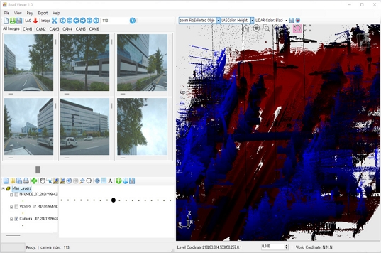
The core functions of the developed system include data overlay, sensor data synchronization, object count analysis, layer selection, zooming, LAS visualization, and SHP visualization. Fig. 1. shows the user interface configured to integrate LAS, LiDAR, camera, and road register SHP data on a location basis.
User interface of the developed road register inspection support viewer
3.2. Transformation of LiDAR to Absolute Coordinates
LiDAR points are originally represented in the sensor coordinate system and therefore must be transformed into a common absolute coordinate system before they can be directly overlaid with road register SHP and LAS data. Let PL denote a point in the LiDAR coordinate system, TVL the sensor calibration transformation from the LiDAR coordinate system to the vehicle coordinate system, and TWV the GPS/INS transformation from the vehicle coordinate system to the world coordinate system. The corresponding LiDAR point PW in world coordinates is calculated as follows:
| (Eq. 1) |
Here, each point is represented using homogeneous coordinates as follows:
| (Eq. 2) |
Each coordinate transformation is represented by a 4×4 homogeneous transformation matrix containing rotation and translation, generally expressed as follows:
| (Eq. 3) |
Here, R is the rotation matrix andtis the translation vector. The transformation matrix TWV was constructed using the position information and roll, pitch, and heading provided by the GPS/INS, while TVL was constructed using the pre calibrated sensor transformation between the LiDAR and the vehicle. Through these transformations, LiDAR frames acquired at different times during vehicle motion can be transformed into a common absolute coordinate system and visualized together with the LAS data, road register SHP data, and GPS trajectory.
3.3. Registration of Camera Images and 3D Objects
To project road register objects onto camera images, a 3D point in the world coordinate system must first be transformed into the camera coordinate system and then projected onto the two-dimensional image plane.
A point in the world coordinate system is represented as
| (Eq. 4) |
The corresponding point in the camera coordinate system is calculated as
| (Eq. 5) |
where RCW and tCW are the rotation matrix and translation vector, respectively, for transforming a point from the world coordinate system W to the camera coordinate system C.
The resulting point in the camera coordinate system is represented as
| (Eq. 6) |
The image coordinates (u, v) are then obtained by applying the camera intrinsic matrix K:
| (Eq. 7) |
where s is the homogeneous scale factor.
The camera intrinsic matrix is expressed as
| (Eq. 8) |
where fx and fy are the focal lengths in the x and y directions, respectively, and (cx, cy) represents the principal point of the image.
Expanding Eq. (7), the actual pixel coordinates are calculated as
| (Eq. 9) |
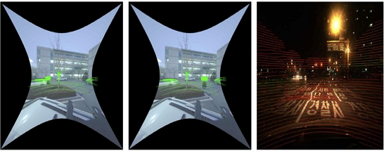
Accordingly, road register objects in the world coordinate system are transformed into the camera coordinate system and subsequently projected onto pixel coordinates in the camera image. This enables inspectors to directly compare the positional and geometric relationships between actual road facilities observed in the camera image and the corresponding road register objects. Fig. 2. shows the results of overlaying and synchronizing camera imagery, LiDAR data, and road register SHP data based on this coordinate transformation.
Example of Camera–LiDAR–SHP overlay and synchronization
3.4. Three-Dimensional Conversion of Road Register SHP
The SHP objects in the road register are represented as Point, Line, and Polygon geometries according to their spatial characteristics. Point objects were converted from individual location coordinates into 3D points, while Line objects were represented as 3D polylines by connecting their vertices. Polygon objects were represented as areas based on their boundaries.
Some SHP datasets contain only two-dimensional geospatial information and do not include elevation data. When these objects are displayed at the same elevation as the LAS data, their visibility may be reduced due to overlap with the point cloud. Therefore, the developed system allows users to specify the display height of SHP objects.
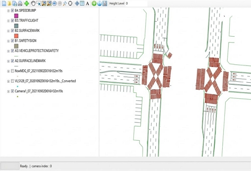
In addition, references to the original SHP features were preserved for the objects converted into 3D. Thus, when a user selects a facility in the 3D view, the corresponding road register attribute information can be retrieved. Fig. 3. shows the representation of Point, Line, and Polygon layers and the user-defined height adjustment function.
Visualization of point, line, and polygon SHP layers with user-defined height
4. Implementation of Road Register Inspection Support Functions
4.1. Integrated User Interface
For road register inspection, it is important to verify the positional and geometric relationships between actual field conditions and road register objects at a specific spatial location. Accordingly, this study developed a location-based integrated interface consisting primarily of a GIS view, 3D view, and Camera view. These views are linked using common location information, enabling integrated comparison and inspection of road register geospatial data, 3D point clouds, and field imagery.
The GIS view displays road register layers and data acquisition locations, while the 3D View enables users to examine the three-dimensional positions and geometries of roads and facilities using LAS or LiDAR data. The Camera view provides actual field images acquired at the corresponding locations.
Because the three views are linked based on the same location information, users can perform road register inspection within a single application without switching among separate GIS, point cloud, and image viewers.
4.2. Selective Display of Road Register Layers
Road registers consist of various road and facility layers. If all layers are displayed simultaneously over LAS and camera imagery, excessive overlap may make inspection targets difficult to identify.
To address this issue, the viewer allows the display status of each road register layer to be selected. When the visibility of a specific layer is changed in the GIS view, the same state is reflected in the 3D view and Camera view.
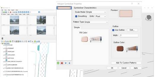
This allows inspectors to selectively display only the objects currently being inspected, such as bridges, medians, road signs, street lights, traffic signals, or other facilities. Layer colors can also be adjusted to facilitate visual distinction among different objects. Fig. 4. shows the selective display implementation using layer checkboxes and color settings.
Selective display and color setting of road register layers
4.3. LAS Data Visualization
LAS data may consist of millions of points, making it difficult to intuitively distinguish roads and surrounding facilities when displayed in a single color.
In this study, two visualization methods were implemented: color representation based on the elevation of LAS points and color representation based on LiDAR intensity.
For height-based visualization, the range between the minimum and maximum elevations of the entire point cloud was divided into a predefined number of intervals, and each point was assigned a color according to its elevation. This enables visual differentiation of elevation differences among the ground, vehicles, road signs, street lights, and surrounding structures.
For intensity-based visualization, different colors were assigned according to the reflectance intensity of each point. Because LiDAR intensity is related to the reflective characteristics of target surfaces, it can be used to distinguish pavement markings and certain traffic facilities from the surrounding road surface. Previous studies on mobile LiDAR-based road inventory have also utilized 3D point cloud information, including intensity, for the analysis of roads and road facilities [10].
In this study, intensity information was used to support visual interpretation by inspectors rather than for automatic object recognition. Fig. 5. shows the visualization results of the same LAS data based on elevation and intensity, along with an example of color linkage with GIS layers.
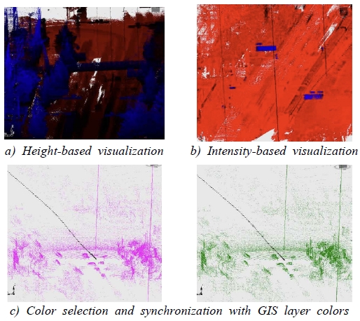
Height- and intensity-based LAS visualization and GIS color linkage
4.4. Zoom and Object Navigation
Road register inspection often requires examination of small objects such as signs and pavement markings. The 3D view therefore provides functions for viewing the full extent, zooming to a selected object, and zooming to a specified area.
The Camera view also provides zoom-in and zoom-out functions so that users can examine the relationship between road register objects and actual field imagery in greater detail. These functions are particularly useful for identifying small road facilities or inspection targets in areas with dense objects. Fig. 6. shows the zoom and selected-object-centered navigation functions implemented in the 3D view and Camera view.
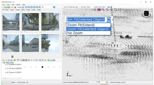
Zoom and object-focused inspection functions
4.5 Object and Inspection Result Management
When SHP data are loaded, the viewer analyzes the number of objects in each layer. An inspection field is added to the existing SHP attribute information so that users can store inspection results after comparing field information with the road register. Inspection results can be extended to states such as normal, object not found in the field, modification required, or new registration required. In the current implementation, these states are not automatically determined by an algorithm; instead, inspectors make the decision directly by comparing the road register objects with LAS point clouds and camera imagery. This constitutes a human-in-the-loop (HITL) approach that supports professional judgment rather than relying on automatic determination. In the implemented system, an inspection field is added to the SHP attribute table, as shown in Fig. 7, so that the existence status and inspection result of each object can be recorded and stored. The inspection states were defined based on visual comparison between road register objects and field information. “Normal” indicates that the registered object is confirmed in the field, while “Object not found in the field” indicates that it cannot be identified. “Modification required” indicates differences in location, geometry, or attributes, and “New registration required” indicates a field object without a corresponding road register object. The final status is determined by the inspector.
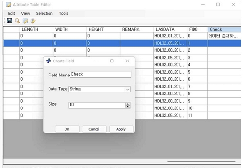
Recording inspection results in the SHP attribute table
5. Performance Evaluation
The developed road register inspection support viewer must process large LAS, LiDAR, and camera datasets in practical inspection tasks; therefore, system performance was evaluated primarily in terms of data processing speed. The test environment consisted of an Intel Core i7-11700KF CPU, 48GB RAM, and an NVIDIA GeForce RTX 3060 Ti GPU. The test datasets consisted of 5.41GB of LAS data, 3.45GB of LiDAR data, and 16.9GB of camera data. The evaluation metrics were data loading, SHP overlay, and coordinate transformation. The performance targets were based on the system performance requirements specified by LX (Korea Land and Geospatial Informatix Corporation), the commissioning organization of the road register inspection program development project. Accordingly, the development targets were set to ≤3s/GB for LAS loading and ≤0.5s/image for both SHP overlay and coordinate transformation.
The data loading results are presented in Table 1. The 5.41GB LAS dataset required 13.832s to load, corresponding to approximately 2.55s/GB and satisfying the target of ≤3s/GB. The 3.45GB LiDAR dataset was processed in 0.420s, corresponding to 0.12s/GB, while the 16.9 GB camera dataset was processed in 0.773s, corresponding to 0.046s/GB. The relatively longer LAS processing time is attributable to reading XYZ coordinates and intensity values for the entire point cloud and constructing the point cloud structure required for 3D rendering.

Data loading performance
The performance of overlaying road register SHP data on camera images was evaluated using six images. The total processing time was 2.873s, corresponding to an average of approximately 0.479s per image, or 0.48s/image when rounded. This satisfied the target of ≤0.5s/image. The result indicates that the system provides sufficient basic processing performance to redraw road register objects on the camera image when the camera frame changes.
Coordinate transformation performance for linking LiDAR and road register data with camera imagery was evaluated using the same six images. The total coordinate transformation time was 2.963s, corresponding to an average of approximately 0.494s/image and satisfying the target of ≤0.5s/image.
Overall, all performance targets for LAS loading, SHP overlay, and coordinate transformation were satisfied (Table 2.). In particular, the system achieved the predefined processing performance not only for large LAS and camera datasets but also for location-based SHP overlay and coordinate transformation, confirming that the developed system provides the basic performance required for integrated inspection of road register geospatial information and field sensor data.
Data loading performance
6. Conclusions
This study developed a road register inspection support viewer for efficiently comparing and reviewing existing geospatial information and current field information during continuous road register updating. The developed system integrates road register SHP with LAS, LiDAR, camera, and GPS/INS data on a location basis, enabling diverse road register objects and current field information to be inspected within a single environment.
Performance evaluation showed that the 5.41GB LAS dataset was processed at 2.55s/GB, while LiDAR and camera data were processed at 0.12s/GB and 0.046s/GB, respectively. SHP overlay and coordinate transformation required approximately 0.48s/image and 0.494s/image, respectively, satisfying all performance targets established during system development. These results confirm the basic processing capability required to integrate large geospatial and field sensor datasets.
The main contribution of this study is the implementation of an integrated inspection environment for determining whether road register information corresponds to current field conditions after construction or updating. In particular, Point, Line, and Polygon road register geospatial data are linked with 3D point clouds and field imagery, providing a technical basis for geospatial quality inspection during continuous road register updating. The current system supports inspectors in visually comparing road register objects with field information; however, it does not yet include automated object recognition, discrepancy detection, or error flagging. Therefore, the term semi-automated inspection in this study refers to the establishment of a technical framework that can be extended toward semi-automated inspection rather than a fully implemented automated inspection function.
However, because the present study focused on system implementation and processing performance, additional validation is required for actual road register error detection accuracy and work efficiency compared with conventional inspection methods. In particular, future studies should use larger and more diverse datasets collected from different road environments and evaluate system performance under multiple hardware configurations. The capability of the system to identify actual discrepancies between road register data and field conditions should also be quantitatively validated. Future work should evaluate inspection accuracy using ground truth data and analyze inspection efficiency through user-based experiments. Object recognition using 3D point clouds and camera imagery should also be integrated with spatial matching of existing road register objects. Based on these functions, automatic discrepancy detection and error-flagging algorithms will be developed to identify and prioritize potentially inconsistent road register objects. These extensions could support development of a semi-automated road register inspection and updating system that automatically prioritizes objects with a high probability of error for inspector review.
References
-
H.S. Lee, A study on the integrated management of national road information- Case of road register -, Journal of Korean Cadastre Information Association, 24(3), 2022, pp.75-83.
[https://doi.org/10.46416/JKCIA.2022.12.24.3.75]

- S.P. Shin, D.G. Yun, A study on the construction of the national highway register using mobile mapping system with automatic drawing generation technology, Korea: Conference Journal of KSCE Convention, 2014, pp.1719-1720.
- S.P. Shin, A study on the support system for frequent renewal of road registers and road construction site safety management system based on mobile, Korea: Proceedings of the 2022 Fall Conference of the Korean Institute of Communications and Information Sciences, 2022.
-
J.H. Kim et al., Development and evaluation of auto-updating system for geo-spatial information of road facilities based on LiDAR technique, Journal of Korean Society for Geospatial Information Science, 31(4), 2023, pp.95-105.
[https://doi.org/10.7319/kogsis.2023.31.4.095]
-
M. Gerke et al., Graph-supported verification of road databases, ISPRS Journal of Photogrammetry and Remote Sensing, 58(3-4), 2004, pp.152-165.
[https://doi.org/10.1016/j.isprsjprs.2003.09.003]
-
T. Strain, R.E. Wilson, R. Littleworth, Computer vision for rapid updating of the highway asset inventory, Transportation Research Record, 2674(9), 2020, pp.245-255.
[https://doi.org/10.1177/0361198120928348]
- Ministry of Land, Infrastructure and Transport, Guidelines for road register preparation, 2024.
-
M. Buuveibaatar, M.G. Kim, S.P. Shin, Towards application of landinfra standard for highway management in Korea, The International Archives of the Photogrammetry, Remote Sensing and Spatial Information Sciences, XLIII-B4-2020, 2020, pp.435-439.
[https://doi.org/10.5194/isprs-archives-XLIII-B4-2020-435-2020]
-
N. Sairam, S. Nagarajan, S. Ornitz, Development of mobile mapping system for 3D road asset inventory, Sensors, 16(3), 2016, 367.
[https://doi.org/10.3390/s16030367]
-
H. Tardy et al., Automatic road inventory using a low-cost mobile mapping system and based on a semantic segmentation deep learning model, Remote Sensing, 15(5), 2023, 1351.
[https://doi.org/10.3390/rs15051351]