Calculation of Outdoor Air Fraction through Economizer Control Types during Intermediate Season
ⓒCopyright Korea Institute of Ecological Architecture and Environment
Abstract
In this study, we examined outdoor air fraction using historical data of actual Air Handling Unit (AHU) in the existing building during intermediate season and analyzed optimal outdoor air fraction by control types for economizer.
Control types for economizer which was used in analysis are No Economizer(NE), Differential Dry-bulb Temperature(DT), Diffrential Enthalpy(DE), Differential Dry-bulb Temperature+Differential Enthalpy(DTDE), and Differential Enthalpy+Differential Dry-bulb Temperature (DEDT). In addition, the system heating and cooling load were analyzed by calculating the outdoor air fraction through existing AHU operating method and control types for economizer.
Optimized outdoor air fraction through control types was the lowest in March and distribution over 50% was shown in May. In case of DE control type, outdoor air fraction was the highest of other control types and the value was average 63% in May. System heating load was shown the lowest value in NE, however, system cooling load was shown 1.7 times higher than DT control type and 5 times higher than DE control type. For system heating load, DT and DTDE is similar during intermediate season. However, system cooling load was shown 3 times higher than DE and DEDT. Accordingly, it was found as the method to save cooling energy most efficiently with DE control considering enthalpy of outdoor air and return air in intermediate season.
Keywords:
Air handling Unit, Intermediate season, Economizer Control, Outdoor Air Fraction1. Introduction
The building sector accounted for 20% of Korean energy consumption in 2014, and more than 45% of them are used as HVAC (Heating, Ventilating, and Air-Conditioning) [1]. In order to conserve building energy, efforts to understand HVAC operation and to apply the theoretical operating saving measures are needed more.
As an energy saving plan in the HVAC field of buildings, there are Duty Cycle, Night Purge, Economizer Control, Optimal Start and Stop, Setback Temperature, etc. [2] and among them, Economizer control, as a general operating method of Air Handling Unit (AHU) to save cooling energy according to the condition of the outdoor air, means free-cooling without machine cooling introducing outdoor air when the outdoor air temperature is lower than the supply air setting temperature. The such outdoor air flow helps not only to save the cooling energy but also to improve indoor air quality [3].
Korea usually performs heating and cooling according to the outdoor air condition in the spring and autumn, during intermediate season, and carries out the cooling energy saving by the Economizer Control at this time. However, in the case of old existing building, reality in the outdoor air flow rate is controlling the outdoor air damper by empirical judgment of the building manager who monitors the outdoor air condition, room temperature and CO2, etc.[4].
The studies to save building energy through Economizer Control are as follows.
Y. Yao and Wang investigated and evaluated the economizer cycle through temperature and enthalpy in VAV (Variable Air Volume) system using a simulation program [5]. AA Chowdhury analyzed the pre-cooling and the efficiency of Economizer Control using return air temperature [6].
Son and Lee al analyzed the energy performance according to the Economizer Control method such as Differential Dry-Bulb Temperature (DT), Differential Enthalpy (DE) and NE (No Economizer) in the office building [7].
Taylor and Cheng analyzed the error and energy savings of Economizer High Limit Control ing the climate throughout the United States [8], L. Gang Wang used internet meteorological data to solve the error of the humidity sensor, and analyzed the optimal High Limit Curve[9]. M.L. G. Wang compared the energy consumption in the air conditioner's Economizer mode and the minimum outdoor air flow rate mode [10].
Although many studies on Economizer Control have been conducted as above, most of the results have been obtained by using simulation program rather than actual air conditioner operation data, and there has been no analysis on the operating pattern and outdoor air flow rate of the AHU actually applied to existing buildings or research on calculation of optimum outdoor air flow rate.
In this study, we examined outdoor air flow rate in Spring during intermediate season using the actual AHU data of the existing building and calculated and analyzed optimum outdoor air flow rate for Economizer Control type. In addition, we examined the energy saving Economizer Control type by analyzing and comparing the recalculated system load through actual heating/cooling operation time and outdoor air flow rate during intermediate season.
2. Building under study
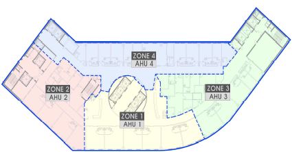
The building is a hospital located in Korea, and five floors are planned as patient rooms, and four AHU serve cooling, heating, and ventilation by dividing zoning by bearing as shown in Fig. 1. The patient room is open 24 hours a day and occupies the largest portion of HVAC energy usage throughout the hospital.
Fig. 1 is a plane view in which four AHUs are composed of respective air handling zones, and all of the five floors are in the same plane. In this study, we examined four AHUs that are responsible for the patient room, not the hospital whole AHUs.
Table 1 shows the conditioned area, fan air flow rate and heating/cooling coil capacity of the four AHUs. Here, the conditioned area is an area including five floors.
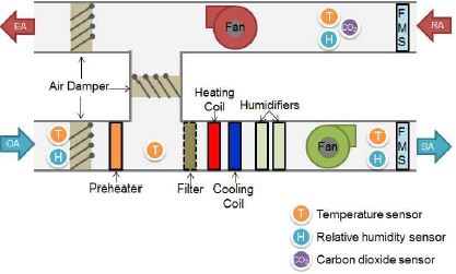
Fig.2 shows the AHU components of building such as damper, filter, cooling/heating coil, fan, humidifier, temperature sensor, humidity sensor and CO2 sensor. The temperature and humidity of supply air, return air, outdoor air, and mixing temperature to mix outdoor air and return air can be known through each sensor.
Through the AHU, the air flow rate of the supply air fan and the return air fan and the valve opening and closing rate of the heating coil and the cooling coil can be confirmed. The supply air temperature varies instantaneously depending on indoor heat generation, solar heat gain, and indoor setting conditions. The supply air temperature is adjusted according to the change of ventilation volume and the opening/closing rate of the coil valve. The mixed air condition varies according to the proper damper adjustment of the outdoor air and the return air, and the system load is generated in order to adjust the mixed air to the supply air setting state. Since the return air temperature remains at a constant temperature, the condition of the mixed air varies according to outdoor air fraction.
When the mixing rate of the outdoor air is lowered, the mixed air condition is similar to the return air condition, and when the mixing rate of the outdoor air is increased, it becomes similar to the outdoor air condition. Therefore, it is possible to save the building energy by introducing the optimum outdoor air flow according to the state of the supply air setting point.
3. Economizer Control type
The Economizer Control type used in this study is as shown in Fig.3 ~ 6 and shows outdoor air flow rate by each type according to outdoor air condition.
3.1. Minimum Outdoor Air Fraction (No Economizer, NE)
The NE maintains the minimum requirement of outdoor air fraction without considering the outdoor air condition. The minimum outdoor air fraction in this building is 30%.
3.2. Temperature Difference Setting (Differential Dry-bulb Temperature, DT)
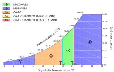
Fig. 3 shows a schematic diagram of the psychrometric chart for the DT control method. Even if outdoor air temperature is lower than the return air temperature, outdoor air flow rate varies depending on where supply air temperature is located on the psychrometric chart. In case the return air temperature was 26 ℃ and the supply air temperature was 20 ℃, the range of outdoor air temperature was shown on the psychrometric chart. The outdoor air flow rate was classified by color and number according to the outdoor air temperature. The boundary point of minimum outdoor air fraction is the outdoor air temperature of 6°C (dotted line), and when the outdoor air temperature is less than 6°C (area ②), the minimum outdoor air flow rate is supplied. The optimum outdoor air fraction is calculated as Eq. (1) for the outdoor air temperature ranged from 6°C to 20°C (area ③). There is no need for machine cooling when the outdoor air flow rate calculated by the Eq. (1) is supplied. When the outdoor air temperature is higher than the supply air temperature (① area), the outdoor air fraction is set to the maximum (100%). That is, the mixing temperature of the outdoor air temperature and the return air temperature becomes the outdoor air temperature, and machine cooling is required in this area.
| (1) |
3.3. Enthalpy Difference Setting (Differential Enthalpy, DE)
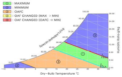
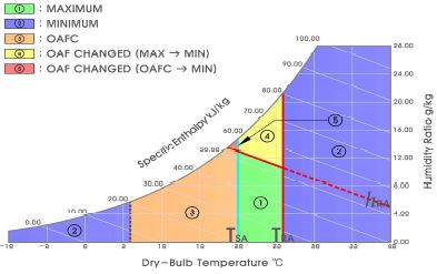
The DE control method compares the enthalpy and eliminates or reduces the cooling load by outdoor air when the outdoor air enthalpy is lower than the return air enthalpy. Fig. 4 shows a schematic diagram of the DE control method on the psychrometric chart.
In the same concept as DT, enthalpy instead of temperature was used. Assuming that the return air enthalpy is 53 kJ/kg (26°C, absolute humidity: 10.5g /kg) and the supply air setting enthalpy is 38.5 kJ/kg (20°C, absolute humidity: 7.3 g/kg), when outdoor air enthalpy is lower than supply air enthalpy (③), the optimum outdoor air fraction is calculated as Eq.(2), and additional machine cooling is not required. When the outdoor air enthalpy is between the return air enthalpy and the supply air enthalpy (area ①), the outdoor air fraction is maximized so that the machine cooling can be used the least. In other words, it is advantageous from the viewpoint of energy that the mixing enthalpy is made to be the outdoor air enthalpy by 100% outdoor air intake. It is the best to close the outdoor air damper in terms of energy saving in case the outdoor air enthalpy is higher than the return air enthalpy (area ②). However, since the minimum outdoor air fraction must be maintained, the mixing enthalpy exists mixed air condition at a position considering the outdoor air enthalpy of 30%.
| (2) |
3.4. Enthalpy High Limit Method for Temperature Difference Setting (Differential Dry-bulb Temperature + Differential Enthalpy, DTDE)
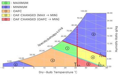
DTDE is a method to use two control methods. This control is the method considering the temperature first the same as DT control, then controlling the return air enthalpy at the high limit, which is shown in Fig. 5. When the temperature is compared, outdoor air fraction need to intake up to 100%, but in the case of the enthalpy side, the area (area ④) where the minimum outside air flow rate need to be maintained is generated. In other words, although the outdoor air temperature is lower than the return air temperature, the outdoor air enthalpy is higher than the return air enthalpy, so it can be seen that it is changed into the minimum outdoor air fraction. Since the outdoor air temperature area is lower than the air supply setting temperature, the area (⑤) to calculate the outdoor air fraction is also the portion that is changed to the minimum outside air flow rate in the enthalpy high limit control. It can be seen that the optimum outdoor air fraction should be considered as the minimum outdoor air flow rate for the areas where the temperature is satisfactory but the humidity is high, so the enthalpy increases.
3.5. Temperature High Limit Method for Enthalpy Difference Setting (Differential Enthalpy + Differential Dry-bulb Temperature, DEDT)
The DEDT is the same concept as in Section 3.4, but the method to control the high limit at the return air temperature based on the enthalpy, which is shown in Fig. 6. This control method is a method changed from the maximum outdoor air fraction to the minimum outdoor air fraction under the outside air conditions of the two areas (area ④ and area ⑤). From the viewpoint of enthalpy, it is possible to maintain the maximum outdoor air fraction, but it is changed to the minimum outdoor air fraction due to the high limit of the return air temperature. Although the energy is expected to increase rather than the enthalpy control, it examined the quantitative estimation of the system load with the DEDT control type and how much the outdoor air conditions corresponding to the area ④ and area ⑤ exist during intermediate season.
4. Measurement Data Analysis During Intermediate Season
4.1. Cooling/Heating Operation Time
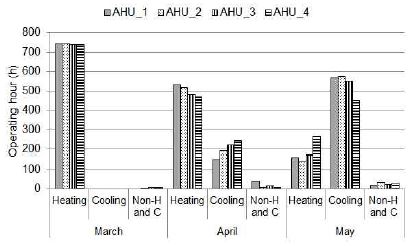
The operation time of heating and cooling were investigated through historical data of each AHU. As shown in Fig. 7, it can be seen that in March, heating was mainly performed and cooling was not performed. In April, it can be seen that the heating time was more than twice as much as the cooling time, and cooling is mainly performed in May.
When examining the air-handling operation time of the building, 1400 hours of heating and 700 hours or more of cooling were found during intermediate season. This operation time intend to be examined in this study because the outdoor air fraction influences the system load depending on the type of Economizer Control.
4.2. Temperature (Outdoor Air, Supply Air, Return Air) and Outdoor Air Fraction
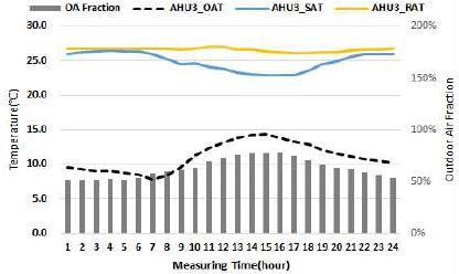
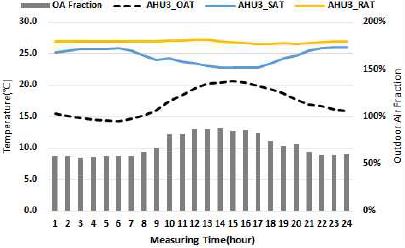
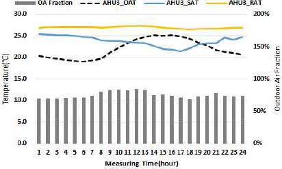
One of the four AHUs operated in the building was selected and the monthly time-averaged outdoor air temperature, air supply temperature, return air temperature, and outdoor air fraction from March to May, intermediate season, are shown in Fig. 8-10.
Fig. 8 shows the average state of each hour in March, and the average outdoor air fraction was 63%. The outdoor air fraction was relatively low in the area where the outdoor air temperature was relatively low during the analysis time, and was high in the area where the outdoor air temperature was high, which shows the increase / decrease pattern according to outdoor air temperature.
The average state over time in April is shown in Fig. 9. The average outdoor air fraction was 69.2%, which was higher than that of March, and shows the increase /decrease pattern according to the change of outdoor air temperature. Fig. 10 shows the average state by time in May. The average outdoor air fraction was 75.2%, which is the highest in the analysis period. The pattern of increase and decrease of the outdoor air fraction shows a low distribution when the outside air temperature is low, and a increased distribution when the outside air temperature is high, and in the area where the outdoor air temperature exceeds the room supply air temperature, it shows a decreasing pattern.
5. Results according to Each Control Type
5.1. Outdoor Air Fraction
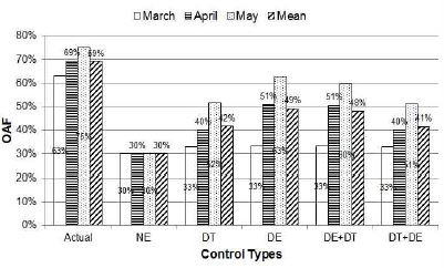
The outdoor air fraction by time of each control type is calculated by the method mentioned in Chapter 3 and Fig. 11 shows the average outdoor air fraction by month. It can be seen that the status of outdoor air fraction of actual AHU shows higher distribution than the five control types, and it is not the energy saving outdoor air fraction, but the excessive outdoor air flow rate. Examining the five control types, the outdoor air fraction was estimated lower in March during intermediate season, and more than 50% in May.
In the four control types excluding the NE in Spring during intermediate season in the building, outdoor air fraction of DT showed an average of 42%, DE, 49%, DEDT, 48% and DTDE, 41%. In DE control type, the average outdoor air fraction was 63% in May, which was calculated highest.
5.2. System Loads
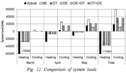
Fig. 12 shows that the outdoor air fraction was calculated according to each control type and the system load using Eq. (3) was calculated by month.
| (3) |
It can be seen that in the actual operation mode, the system heating load was three times higher than that of the other control types in the intermediate season. When operating with the minimum outdoor air flow rate (NE), the system heating load showed the lowest distribution, but the system cooling load was 1.6 times higher than that of DT and 5 times higher than that of the DE control method. Therefore, it can be seen that while the heating energy is advantageous when operating with the minimum outdoor air flow rate, the cooling energy may be more than five times higher.
DT and DTDE were similar to DE and DEDT in heating load, but three times higher in cooling load. Therefore, the DE control method considering the enthalpy of outdoor air and return air was analyzed in the way that the cooling energy was conserved the most during intermediate season.
Examining the heating and cooling system load in March, the outdoor air fraction was estimated to be 30 ~ 33% through five control methods, and the system heating load showed a similar distribution. The system cooling load of NE and DT was 2,965 kW and 501 kW, respectively. In the case of DE, the system cooling load did not occur because the outdoor air fraction was optimized calculated. In this way, it is possible to save the cooling energy by performing the outdoor air cooling through the DE control method, which can occur in March, and it can be seen that the DT system requires some cooling.
In the case of DT and DTDE control method in April, heating load is similar to DE and DEDT, but cooling load of DT and DTDE is more than 30 times higher than that of DE. In other words, in Korea, it can be seen that the cooling energy can be saved the most by the Economizer DE and DEDT control method in April. Compared with the NE method using the minimum outdoor air flow rate, the DE control method can reduce the cooling load by 24,211 kW, which is more than the 21,388 kW that reduced the cooling load in the same way in May.
5. Conclusion
In this study, we investigated the outdoor air flow rate in spring, using the historical AHU data of existing buildings, and analyzed the optimal outdoor air flow rate for Economizer Control type.
- (1) As for the application status of outdoor air fraction of the building, it shows high with 63% in March, 69% in April, and 75% in May.
- (2) As a result of examining outdoor air temperature, supply air temperature, return air temperature, and outdoor air fraction, the outdoor air fraction tended to increase when the outdoor air temperature was high in March and April, and the outdoor air fraction showed the pattern to decrease when the outdoor air temperature was higher than supply air setting temperature in May.
- (3) As a result of calculating the optimum outdoor air flow rate by applying five Economizer Control methods, the outdoor air fraction was estimated to be low in March and showed more than 50% in May. For the DE control method, the highest outdoor air fraction was calculated as 63% in May.
- (4) When the minimum outdoor air flow rate is operated during intermediate season, since it is shown 1.6 times higher than DT control method and 5 times higher than the DE control method in the system cooling load, it is necessary to calculate proper outdoor air flow rate.
- (5) During intermediate season, DT and DTDE control method is similar to DE and DEDT control method, but three times higher in cooling load.
Therefore, the DE control method considering the outdoor air and return air enthalpy was shown as a method to save the cooling energy most during intermediate season, and the cooling energy saved in April was more than that in May.
The research on the operation of energy saving air-handling system in addition to Economizer Control method will be more actively needed in the future.
Acknowledgments
This research was supported by Basic Science Research program through the National Research Foundation of Korea(NRF) funded by the Ministry of Education(No.2015 R1D1A1A01057928).
References
- 2014 Energy Consumption Survey, Korea Energy Economics Institute.
- J.H. Huh, “Building Energy Management”, KIASEBS, 4(2), p18-24.
-
G. Wang, L. Song, Air handling unit supply air temperature optimal control during economizer cycles, Energy and Buildings, 49, (2012), p310-316.
[https://doi.org/10.1016/j.enbuild.2012.02.024]

- C.S.P. W.J. Suh, Issues and Limitations on the Use of a Whole Building Simulation Tool for Energy Diagnosis of a Real-life Building, AIK, 28(1), (2012), p273-283.
-
Y. Yao, L. Wang, Energy analysis on VAV system with different air-side economizers in China, Energy and Buildings, 42(8), (2010), p1220-1230.
[https://doi.org/10.1016/j.enbuild.2010.02.013]

-
A.A. Chowdhury, M.G. Rasul, M.M.K. Khan, Modelling and analysis of air-cooled reciprocating chiller and demand energy savings using passive cooling, Applied Thermal Engineering, 29(8-9), (2009), p1825-1830.
[https://doi.org/10.1016/j.applthermaleng.2008.09.001]

-
J.E. Son, K.H. Lee, Cooling energy performance analysis depending on the economizer cycle control methods in an office building, Energy and Buildings, 120, (2016), p45-57.
[https://doi.org/10.1016/j.enbuild.2016.03.073]

- C.H.C. Steven , T. Taylor, Economizer High Limit Controls and Why Enthalpy Economizers Don't Work, ASHRAE, 52(11), (2010).
- Gang Wang, L.S., Energy Analysis, Optimal High-Limit Control and Engineering Approach of Air-Side Economizers, ASHRAE Transactions, 120, (2014), p383-396.
- Wang, M.L. G., Optimal Outside Air Control for Air Handling Units with Humidity Control, Proceedings of International Conference for Enhanced Building Operations, (2006).
