Sensitive analysis of design factor for the optimum design of PVT system
ⓒ Copyright Korea Institute of Ecological Architecture and Environment
Abstract
Recently, renewable energy system has been widely used to reduce the energy consumption and CO2 emission of building. A photovoltaic/thermal(PVT) system is a kind of efficient energy uses, which is combined with photovoltaic module and solar thermal collector. PVT system removes heat from PV module by through thermal fluid to raise the performance efficiency of the PV system. However, though PVT system has the merit of the improved efficiency in theoretical approach, there have been few performance analysis for PVT system using the dynamic energy simulation. In this study, in order to establish the optimum design method of this system, simulation was conducted by using individual system modules.
For the dynamic simulation, TRNSYS17 was used and local weather data was utilized. Furthermore, the system performance in various installation condition was calculated by case studies.
As a result, the amount of electric generation and heat production in each case was found by the simulation. The gap of system performance was also evident according to the installation condition.
Keywords:
Photovoltaic/Thermal system, Dynamic Simulation, Installation angle, Electrical Performance, Thermal Performance1. Introduction
Recently, the government is inducing voluntary participation in energy saving to deal with skyrocketing energy demand in buildings. Especially, the energy related policies centered on supply mainly are changed into policies centered on demands such as making submission of energy saving plan mandatory in buildings larger than 500㎡ in total size or raising electric fee. Due to this, interests on new and renewable energy is expected to increase and the market for them is as well expected to grow continuously. Photovoltaic market shows decrease in the price of ESS and photovoltaic module as Energy Storage System, ESS, and new, renewable energy industry grows and is predicted to steadily grow with market increase of 14.9% on yearly average from 2013 to 2016. [1]+
Photovoltaic/thermal system is one of technologies that efficiently use photovoltaic energy and a form that photovoltaic module and thermal collection system are combined, being a system that prevents efficiency reduction because of rise in temperature of modules caused by summer insolation by circulating thermal medium such as liquid, air and uses the heat through measurement and retrieval. Design methods using quantitative data are still not enough since the study of liquid PVT system still stays in experimental study stage although air PVT system that use air as a thermal medium through pilot studies until now is at utilization stage in its study level through various interpretation and experimental studies[2]. Study for PVT system has been done for 40 years and the contents are as follows. In 1978, Kren and Russeell presented hybrid system that combined flat photovoltaic collecting collector and photovoltaic module[3], and study on PVT system has been accelerated as interest on new and renewable energy increases all over the world in 1990s. Y. Tripanagnostopoulos at al. conducted study to increase total energy production of PVT system and reported the result that electric performance decreases although thermal performance increases upon usage of glass cover[4]. Zandag H.A at al. presented alternatives for module production of high performance by measuring performance change through various designs of PVT modules showing the highest thermal performance which is 39% in Insulate type among many types of modules presented and obtained the result that electric performance is the highest with 7.6% at sheet-and-tube[5]. In domestic researches, Uh, Seung-Hui and others analyzed and compared photovoltaic energy collector and PV module regarding performance of Glazed and Unglazed PVT system then confirmed performance change by change in entrance temperature of modules[6]. Jung, Sun-Ok and others evaluated heating performance of BIPVT system which is building all-in-one air PVT by considering applying it to roof and outer walls through experiment[7].
Most of studies on PVT system in pilot studies are experimental studies to develop specifications of system proper for installment condition and climate features of installment area and interpretative studies for optimum design are rare. Thus this research confirmed system performance by operation methods of circulation pump of PVT module by using TRNSYS17 which is simulation for active interpretation with the objective of Geo-PVT system development, a hybrid system that PVT system and geothermal system are combined and measured performance under the conditions where a certain amount of convention heat loss is constantly happening to establish design factors. Also, it confirmed system performance change by installment angle of PVT module by regions.
2. Target system summary
PVT system is a form that Photovoltaic (PV) module and Solar collector (SC) are combined and can produce electric and thermal energy at the same time. It can reduce installment area compared to installing each system since it produces electricity and heat at the same time possessing higher energy amount produced by unit area than individual system. PVT module can be classified into air PVT and liquid PVT depending on thermal mediums of circulation and modules are classified into Glazed PVT and Unglazed PVT depending on the presence of glass cover at front of modules. Glazed PVT is a form that glass covers are additionally installed with a certain space in front of PV module with features of low electric performance because of increased temperature of modules despite high heat amount produced through heat loss reduction at module surface and Unglazed PVT is a form that has an ease in cooling of module by convection since its surface meets air having features of high electric performance despite low thermal performance due to heat loss[8].
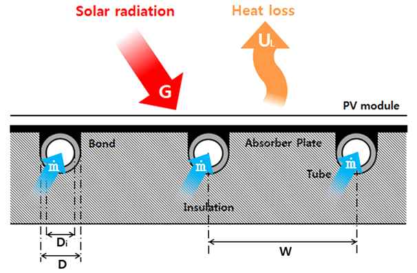
The kind of PVT system used in this system is liquid type Unglazed PVT referring to the system that uses liquid like water or antifreeze as heat mediums. Liquid type Unglazed PVT has a risk of leak or freeze but occupies only little space compared to air type system and it is easy to combine with other heat source system as well as the fact that it can al so be used for protection against heat by radiation of summer night aside from producing heat in daily times. Fig. 1 shows structure of PVT modules.
PVT system that uses solar energy, on the other side, has insolation entered changed depending on the angle and installment location of modules thus its performance can be changed easily. Maximum output of PVT modules possess power amount of 0.5% when temperature of module changes by 1℃ being affected by insolation and surface temperature of solar battery under operation conditions and can be obtained through following equation[9].
| (1) |
Pm (t) : Maximum output under operating conditions (kW/㎡)
Pm : rated output(temperature 25[℃], intensity of solar radiation 1[kw/㎡])
Q : intensity of solar radiation under operating conditions (℃)
t : surface temperature of solar batter under operating conditions (℃)
Decrease in generation amount due to increase in surface temperature can be decreased through heat gain of thermal exchanges and calory gain of Unglazed PVT can be obtained through following equation. Heat amount generated of PVT system is determined by values of calories absorbed of absorber plate of modules (G·α), performance coefficient in heat removal FR, heat loss UL and heat removal performance (FR ) is affected by specific heat and flow, diameter of pipe and interval and heat loss (UL ) can be obtained by adding heat loss rate at front( U t ), back(Ue ), wall (Ub )all together[10].
| (2) |
| (3) |
| (4) |
| (5) |
Q : Calories obtained from heat exchanger
A : heat gain area of PVT modules (㎡)
FR : Performance coefficient in heat removal of PVT modules
G : insolation (W/㎡)
α : Heat absorption rate
UL : heat loss rate (W/㎡℃)
Ti : entrance temperature of PVT modules
Ta : air temperature (℃)
ṁ : flow of circulation water (kg/s)
Cp : specific heat of circulation water (kj/kg℃)
hfi : heat exchange performance between pipe and heat medium
3. Interpretation summary
3.1. Simulation summary
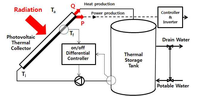
This research did its simulation using TRNSYS 17 which is active interpretation program and simulation model is shown in Fig. 2. The system is composed of PVT module and heat storage tank, circulation pump. PVT module is installed at 45° angle to the south being unglazed type PVT without glass covers and the size of it is 1.644m in length, 0.992m in width, electric performance of photovoltaic module is set as 15.33%. Absorber plate inside the collector is supposed to be of aluminum (heat transfer rate238W/mK) with 3mm in thickness. Heat storage tank is set as 300L, the capacity generally used in the household. Control of circulation pump is set so that pump stops when circulation water is below 2℃ and works when the temperature of PVT module of circulation water and entrance temperature of heat storage tank differs more than 5℃ in temperature difference control method. Flow of circulation water is 120kg/h(0.02kg/㎡s), standard of performance test of photovoltaic collector referring to KS B ISO 9806-1 and Table 1 shows setting condition of PVT system.
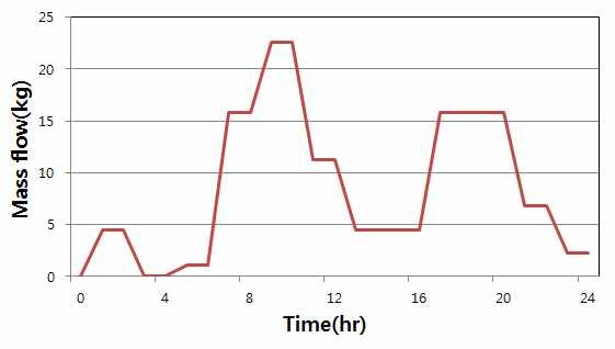
Heat stored in heat storage tank supposed heater load on daily average as 210kg/d and set to use according to the pattern of daily heater load shown in the figure[11], and supplied water of 15℃ for amount of hot water used. Data of Seoul was used as climate conditions for simulation.
3.2. Simulation conditions
Case Study of simulation conducted simulation dividing objective into 4, to establish operation methods and design factors of PVT system, to confirm system performance by conditions for link with other system and the contents are as follows.
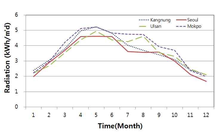
Case1 compared daily energy generation amount by setting halt temperature of circulation temperature in different temperature control as 2℃ and changing the operation temperature to 5℃, 10℃, 15℃ while Case2 compared daily energy generation amount to flow of circulation water through changes. Simulation was done by selecting 120kg/h which is the standard of performance test for photovoltaic energy collector as Base Case for flow and adjusting the conditions to 90kg/h, 200kg/h, 300kg/h. Case3 confirmed changes in generation amount of electricity and heat under the conditions that convection heat loss occurs continuously through changes of transfer coefficient of convection at front PVT modules. Coefficient of convection heat transfer was set to 5.8W/㎡K, 17.4W/㎡K, 29.7W/㎡K under the supposition that breeze, wind at 3m/s, 5m/s continuously blows at front of module each. Case4 compared amount of energy generated by angle from Ulsan, Seoul, Kangrng, Mokpo to check the changes in amount of thermal and electric energy generated by installment angle by regions. Simulation was done by differentiating installment angle of modules into 5 degrees, 15°, 30°, 45°, 60°, 75°. Weather data of Meteonorm from Meteotest company of Swiss was used for weather data of target area and Figure 4 shows daily average insolation by months of target area.
Simulation result showed amount of energy generated on daily average by month classified into electric and thermal generation. And it showed energy usage performance that considered both electricity and heat generation compared to insolation in each cast conditions.
4. Simulation result
4.1. Result by changes in operation temperature of circulation pump
Table 2 shows simulation result by changes in operation temperature of circulation pump. It showed amount of heat and electric energy generated on daily average by month of PVT module with energy usage rate compared to insolation htat considered amount of heat and electric energy generated(ηenergy ). Amount of energy generated was the highest at 5℃ with 2.01kWh/d and at 10℃ and 15℃, it was each 1.97kWh/d and 1.91kWh/d, with pump operation time and energy generation amount decreasing as operation temperature increases. Working hours for pump on daily average was shown to be 4h 38m at (on/off) 5/2℃ and 3h 55m 10/2℃ and 3h 22m at 15/2℃. Amount of electricity generation recorded relatively similar result value and heat production amount was confirmed to be huge in summer where insolation is high with high temperature. Operating hours of pump on daily average was also shown to be large by 2.7 times on average in summer compared to winter.
Comparison of result after dividing amount of energy generated into summer(June, July, August) and winter(December, January, February) shows 10% decrease in amount of energy generated in winter and 6% in summer as working temperature of circulation pump ΔT increases from 5℃to 15℃. It was confirmed that reducing amount of heat loss by shortly running operation cycle of circulation pump in winter where heat loss of PVT module is large is a desirable operation method.
4.2. Result by flow change
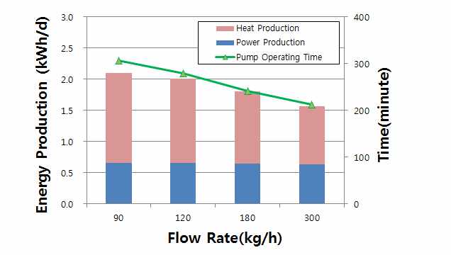
Simulation result by flow change shows 2.10Wh/d of energy generated in 90kg/h, 2.01Wh/d in 120kg/h, 1.81Wh/d in 180kg/h, 1.56Wh/d in 200kg/h and amount of thermal and electric energy generated decreased as flow increased. It was decided reduction in electric energy generation is because of increased surface temperature of module due to decrease in heat loss amount and reduction in heat generation amount was decided to be caused by decreased total operating hours without continuous operation of pump since ΔT at entrance and exit of circulation water decreases as flow increases. Based on the result of Table. 3, there showed difference of about 2h in summer and 1h 20m in winter as a result of comparing operating hours of pumps that are 90kg/h, 300kg/h with biggest difference in the amount of energy generated.
4.3. Result according to convection heat loss change
Case3 that changed heat loss rate of convection confirmed that amount of heat generation decreases and electricity generation increases as heat loss of convection increases. Heat transfer through convection is active since module surface directly meets air because of features of unglazed PVT module without glass cover and heat production amount rapidly decreased as heat transfer coefficient of convection increased in winter where temperature difference between module surface and air temperature is large. Amount of heat generation was each 0.68kWh/d and 0.05kWh/d with 93% decrease under 5.8W/㎡K and 23.7W/㎡K in average of heat production of winter (December, January, February). Amount of electricity produced showed difference by 6% with 0.66kWh/d under 0.63kWh/d under 5.8W/㎡K. Electricity and heat generation amount changed by changes in heat transfer rate of convection in summer as well and electricity generation increased by 2% while heat generation decreased by 21%.
4.4. Result by changes in installment angle and regions
Case4 compared amount of electric and thermal energy generated on daily average monthly by changing installment angle into 15°, 30°, 45°, 60°, 75° targeting 4 regions, Seoul, Kangrng, Ulsan, Mokpo. Comparison of daily insolation on monthly average of target areas shows the highest in Mokpo, 3.84kWh/㎡d, the lowest in Seoul, 3.32kWh/㎡d.
As a simulation result energy generation was shown the biggest at installment angle of 15° in summer when the altitude of sun is high and, 60° in winter when it is low, with yearly average energy generation being the highest at 30°. Energy generation amount by angles of each city showed similar distribution since latitudinal difference between target cities of simulation and Mokpo with the highest daily energy generation on yearly average and Seoul with the lowest of it each showed difference by 22% with 2.48kWh/d and 2.03kWh/d because of effect of air temperature and insolation. Table8~ 11 shows the result of simulation by installment angle of each city.
The generation amount of electricity and heat is each 0.71kWh/d and 1.54kWh/d at installment angle of 30° that show the highest performance upon comparison of energy generation amount by installment angle setting the simulation result of data from 4 cities as averages and it was confirmed to be higher by 23% than that of installment angle of 75° with the lowest energy generation amount. Energy generation amount by seasons shows 1.34kWh/d in winter (January, February, December), 2.94kWh/d in summer (June, July, August) and energy generation amount of summer was as much as 2.2 times that of summer showing big performance difference between seasons. Electricity energy was shown to be 32%, while thermal energy was shown to be 68% in ratio of electric to thermal energy in average energy generation.
5. Conclusion
This research compared and analyzed amount of heat and electricity daily generated by months depending on installment conditions and operation methods of PVT system using TRNSYS17 simulation. System performance change according to changes of each design factor could be checked through simulation result and optimum installment condition and operation method by region and season under simulation conditions could be checked.
(1) The result by changes in ΔT which is temperature control of circulation pump in different temperature control method shows decrease in heat and electricity generation by respectively 2% and 5% as operation temperature increases to 5℃, 10℃, 15℃.
(2) Energy performance by flow change of circulation water decreased as flow increased because of reduced temperature difference at entrance and exit of PVT module and it was confirmed that energy generation decreased due to reduced time of pumping working hours caused by this.
(3) Electricity generation increased and thermal generation decreased as convection heat loss increases as a result of checking effect of convection heat loss at front of Unglazed PVT modules. Daily thermal generation decreased up to 93% monthly under the condition of 29.7W/㎡K in winter where temperature difference between air and average temperature of circulation water is big.
(4) The biggest energy generation was confirmed at 15° in summer, 60° in winter in the result by changes in installment angle of PVT modules. Yearly total energy generation was shown to be the biggest at 30° angle. Energy generation in summer was as much as 2.2 times of winter, helping us know that energy generation of PVT module is largely affected by insolation and air temperature.
It is planned to be reflected in design and empirical experimental for system introduction in the future through comparison and result of performance experiment of PVT module produced for a test based on this simulation result.
Acknowledgments
This work was supported by the New & Renewable Energy Core Technology Program of the Korea Institute of Energy Technology Evaluation and Planning (KETEP), granted financial resource from the Ministry of Trade, Industry & Energy, Republic of Korea. (NO. 20133030110900)
Reference
-
신·재생에너지 동향자료, 에너지관리공단 신·재생에너지 센터, (2014).
Trend of new and renewable energy, energy management corporation New and Renewable Energy Center, (2014). -
김상열, 남유진, “동적 시뮬레이션을 이용한 태양광열 시스템의 성능특성 분석”, 생태환겅건축학회, 15(2), p95-101.
Study on the Analysis Performance of PVT system using the Dynamic, Journal of the KIEAE, (2015, 38), 15(2), p95-101. [2] John A. Duffie, Beckman, William A., ENGINEERING OF THERMAL PROCESSES, 4th edition. - Kern, EC, Russell, MC, Combined Photovoltaic and Thermal Hybrid Collector Systems: Photovoltaic Specialists Conference, (1978).
-
Y. Tripanagnostopoulos, et al , Hybrid Photovoltaic/Thermal Solar Systems, Solar Energy, (2002), 72, p217-234.
[https://doi.org/10.1016/S0038-092X(01)00096-2]

-
Zondag, H.A, de Vries, D.W, van Helden, W.G.J, van Zolingen, R.J.C, The yield of different combined PV-thermal collector designs, (2003), 74(3), p253-269.
[https://doi.org/10.1016/S0038-092X(03)00121-X]

-
어승희, 이정빈, 최윤성, 김대현, “PVT 시스템의 PV 모듈 및 태양열 집열기 대비 성능 및 효율 비교분석", 한국태양에너지학회, 32(2), (2012).
The Performance and Efficiency Analysis of a PVT System Compared with a PV module and a Solar collector, Journal of the Korean Solar Energy Society, (2012), 32(2), p1-10. -
정선옥, 김진희, 김지성, 박세현, 김준태, “실험을 통한 건물통합형 태양광ㆍ열(BIPVT) 시스템의 난방성능 평가”, 한국태양에너지학회, 32(6), (2012).
The Heating Performance Evaluation of Heating System with Building-Integrated Photovoltaic/Thermal Collectors, Journal of the Korean Solar Energy Society, (2012), 32(6), p113-119. [https://doi.org/10.7836/kses.2012.32.6.113]
-
김진희, 김준태, “문헌고찰을 통한 태양광/열 복합 시스템의 유형별 성능특성 비교, 한국건축친환경설비학회, 1(2), (2007).
The Performance Comparison of PVT System through Literature Review, Journal of KIAEBS, (2007), 1(2), p15-21. -
염성배, 최홍규, 최영준, 홍성구, 김태훈, “냉각시스템에 의한 태양광 발전의 효율 개선”, 조명·전기설비학회논문지, 23(5), (2009).
Solar Photovoltaic According to Installation of Cooling System, Journal of the Korean Institute of IIIuminating and Electrical Installation Engineers, (2009), 23(5), p66-71. [https://doi.org/10.5207/JIEIE.2009.23.5.066]
- John A. Duffie, William A. Beckman, Solar Engineering of Thermal Processes, FOURTH EDITION, (2013), 4th Edition.
-
김성민, 정광섭, 김영일, “공동주택의 급탕부하 지속시간 및 부하 패턴에 관한 실증연구”, 에너지 공학, 21(4), (2012).
An Empirical Study of Hot Water Supply Patterns and Peak Time in Apartment Housing with District Heating System, Journal of Energy Engineering, (2012), 21(4). -
Hegazy, Adel A, Comparative study of the performances of four photovoltaic. thermal solar air collectors, Energy Conversion and Management, (2000), 41(8), p861-881.
[https://doi.org/10.1016/S0196-8904(99)00136-3]

-
Coventry, Joe S., Performance of a concentrating photovoltaic / thermal solar collector, Solar Energy, (2005), 78(2), p211-222.
[https://doi.org/10.1016/j.solener.2004.03.014]

-
Chow, T T, Pei, G, Fong, K F, Lin, Z, Chan, A L S, Ji, J, Energy and exergy analysis of photovoltaic-thermal collector with and without glass cover, A ppliedEnergy, 86(3), p310-316, (2009).
[https://doi.org/10.1016/j.apenergy.2008.04.016]

-
Hegazy, Adel A, Comparative study of the performances of four photovoltaic thermal solar air collectors, Energy Conversion and Management, (2000), 41(8), p861-881.
[https://doi.org/10.1016/S0196-8904(99)00136-3]

-
나선익, 강은철, 이의준, “공기식 태양광열기 활용 공기열원 히트펌프 시스템의 성능개선 시뮬레이션 연구”, 대한설비공학회, p963-967, (2013).
Na, Sun-Ik, Kang, Eun-Chul, Lee, Euy-Joon, The PVT Air Integrated Air to Air Heat Pump System Performance Simulation Study, Journal of SAREK, 1(2), (2013). -
He, Wei, Chow, Tin-Tai, Ji, Jie, Lu, Jianping, Pei, Gang, Chan, Lok-shun, Hybrid photovoltaic and thermal solar-collector designed for natural circulation of water, Applied Energy, 83(3), p199-210, (2006).
[https://doi.org/10.1016/j.apenergy.2005.02.007]

-
Fraisse, G, Méenéezo, C, Johannes, K, Energy performance of water hybrid PV/T collectors applied to combisystems of Direct Solar Floor type, Solar Energy, 81, p1426-1438, (2007).
[https://doi.org/10.1016/j.solener.2006.11.017]

-
Dubey, Swapnil, Tiwari, G.N, Thermal modeling of a combined system of photovoltaic thermal(PV/T) solar water heater, Solar Energy, 82, p602-612, (2008).
[https://doi.org/10.1016/j.solener.2008.02.005]

-
Chow, T.T, He, W, Ji, J, Hybrid photovoltaic thermosyphon water heating system for residential application, Solar Energy, 80(3), p298-306, (2010).
[https://doi.org/10.1016/j.solener.2005.02.003]

-
천진아, 김진희, 김준태, 조인수, 남승백, “전면 액체식 흡열판을 적용한 PVT 모듈의 성능실험”, 한국태양에너지학회, 31(1), (2011).
Chun, Jin-Aha, Kim, Jin-Hee, Kim, Jun Tae, Cho, In Soo, Nam, Seung Baeg, A Experimental performance of PVT module with fully wetted absorber, Journal of the Korean solar Energy Society, 31(1), (2011). -
백남춘, 정선영, 윤응상, 이경호, “콤팩트형 태양열/지열히트펌프 하이브리드 냉난방 및 급탕 시스템 개발 및 성능분석”, 한국태양에너지학회, 32(5), (2012).
Baek, N. C., Jeong, S, Y., Yoon, E. S., and Lee, K. H., The development and performance analysis of compact type solar thermal/ground coupled heat pump hybrid system for heating, cooling and hot water, Journal of the Korean Solar Energy Society, (2012), 32(5), p60-67. -
남유진, 태양열 및 지중열원을 이용한 히트펌프 시스템의 최적이용법에 관한 연구, 설비공학회논문집, 24(6), (2012).
Nam, Y. J., (2012), Study on the optimum design of a heat pump system using solar and ground heat, Korean Journal of Air Conditioning and Refrigeration Engineering, 24(6), p509-514.
