A Study on Passive Cooling Strategies for Buildings in Hot Humid Region of Nepal
ⓒ Copyright Korea Institute of Ecological Architecture and Environment
Abstract
Increase in energy consumption in building is a big concern world over. In Nepal, energy crisis is a big issue but energy demand in buildings is barely even thought about. In the southern part of Nepal, where the weather is mostly hot during the year, cooling in buildings is very important. This is an initial study regarding building design strategies which focuses on cooling energy consumption in the building. It can be seen from the study that simple passive strategies can be applied in building design which can support in decreasing cooling load. Different passive cooling strategies like orientation, building size, thermal mass, window design and two direct cooling strategies have been investigated in this study. Direct cooling strategies like shading and natural cooling helps in passive cooling. Different desing strategies have different impact on the cooling energy requirement and the study shows that thermo physical property of building materials has the maximum effect on the energy consumption of the building. Each design strategy creates and average of 20% decrease in energy consumption, whereas the thermal conductivity can have as much as 10 times more effect on the energy consumption than other design strategies.
Keywords:
Passive Design Strategy, Passive Cooling Design, Hot Humid region, Nepal1. Introduction
1.1. Background and purpose of study
Nowadays, buildings are responsible for 40% of electricity consumption, CO2 emissions and waste generation [1]. Many studies and design philosophies regarding decrease in energy consumption in buildings have been done. The foremost design philosophies, that are being followed nowadays like sustainable design and green building design, all focus on lowering energy consumption in buildings using passive design. Passive design makes use of the surrounding resources to provide a comfortable environment inside the building.
Pacheco et el. performed a study on energy-efficient design methods that can be applied to the building to lower energy consumption in the building [2]. The study provides an overview of design criteria that can reduce the energy demand in residential buildings. Tuohy et al. investigated the significance of thermal mass, insulation and ventilation for space heating energy use in sustainable housing [3]. Vincent and John carried out a study on the relation between building materials, building technology and their impact on energy requirement, environment and building occupant [4]. Kumar and Suman studied the effect of passive design techniques like solar shading and building insulation on the decrease in the indoor temperature in three different areas through numerical calculations [5].
In case of Nepal, with energy consumption per capita of 382.64 kg, Nepal is ranked 124th out of 135 countries in the world in 2011 and is ranked 173 out of 191 countries for CO2 emissions at 0.14 metric tons per capita in 2010 [6]. The main source of energy in Nepal is firewood and mostly is used for domestic heating and cooking but main source of energy for cooling is electricity [7]. So, it is not about decreasing energy consumption but increasing efficiency use and not letting the consumption to increase unnecessarily [8].
There are a few studies done regarding building energy consumption and comfort in Nepal. Toffin collected documentation on various vernacular buildings in Nepal and showed how they created comfortable living spaces using local materials and space planning [9]. Bodach et al. studied the climate responsive features in various vernacular buildings in different parts of Nepal [10]. It is a very comprehensive study on passive designs of vernacular building based on both literature and field study. Upadhyaya et al, did a study on the climate responsive features of the vernacular buildings in Kathmandu Valley and suggested some design guidelines for construction in Kathmandu valley based on Bioclimatic chart, Building Bioclimatic chart and Mahoney tables analysis of Kathmandu climate [11]. Rijal et al. carried out a series of empirical studies on the comfort of different vernacular houses in different parts of Nepal [12-16]. His studies show how the vernacular buildings create heating and cooling for a comfortable living space in different climate zones of Nepal.
Due to the energy crisis in Nepal, it is better to have designs which can be independent of mechanical intervention for comfort. So, this study focuses on building design strategies based on passive cooling design for hot and humid region of Nepal.
1.2. Methodology
A research project was conducted in Biratnagar, Nepal to study how the low cost housing construction technology can be improved that was being promoted by Habitat for Humanity Nepal [17,18]. The focus was on improving the comfort level inside the houses by decreasing the indoor temperature by manipulating the building materials. Three houses were built during this study. One of the houses was used for calibrating the base case model for this study. The house used for calibration is 27m2 with two rooms. The floor is made of poured concrete over compacted stone, the walls are made of sundried mud bricks with 25mm air gap between two 250mm brick leaves and the roof is made of 28 gauge corrugated tin sheets with 120mm straw on bamboo rafters. Three hourly temperature and humidity data was taken of the outside temperature and the inside of the house. The simulation model was calibrated using the measured temperature so that the error was 7.15%.
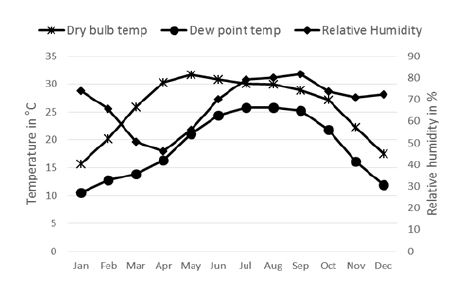
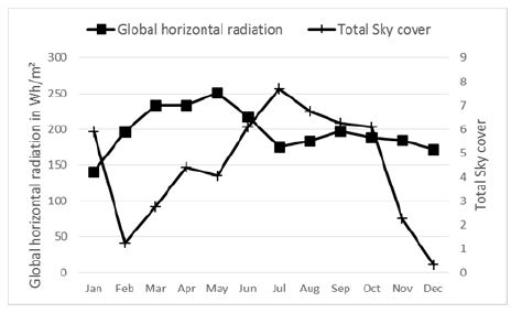
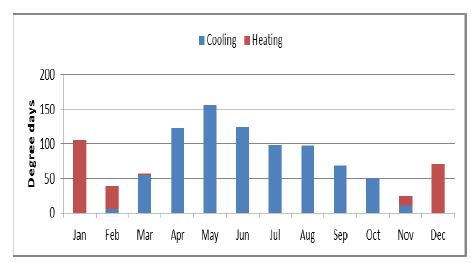
Biratnagar lies in the south east part of Nepal at 26.48N latitude and 87.26E longitude. <Fig. 1> shows the average monthly temperatures from March to October lie over 25°C and can go over 35°C during April to June, all year round the temperature stays well over 10°C and the relative humidity is lowest in April at over 45%, just when the temperature starts increasing, from February to May it remains below 70% and over it the rest of the year. This makes the climate very humid and hot. <Fig. 2> shows the sky remains clear for most of the year except for the rainy season in the months of June to August and receives high solar radiation, an average of 194.09 Wh/m2/day. <Fig.3> shows the heating and cooling degree days for Biratnagar and clearly shows the requirement of cooling during most of the year.
2. Simulation
2.1. Simulation software
EnergyPlus v6.0 has been used for the simulation study. It is a whole building energy simulation developed by US-DOE with its roots in BLAST and DOE-2 [19]. It is an energy analysis and thermal load simulation program. JEPlus, an independent GUI for parametric simulations for EnergyPlus [20], was additionally used for the various parametric studies.
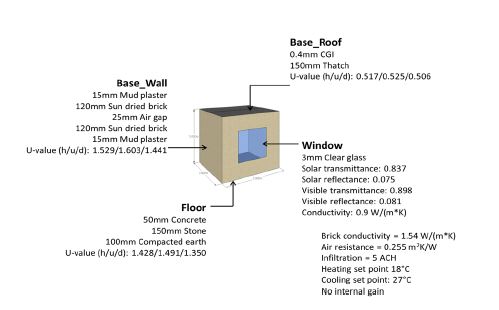
The minimum width for a living space should be 10 ft. or 3 m. as described by Nepal Building code [21], so to simplify the model, the base model used for the study is 3m×3m×3m as seen in <Fig. 4>.
2.2. Simulation overview
The weather data of Biratnagar, Nepal used for simulation was obtained from Meteonorm program. On EnergyPlus official website, it is recommended that Meteonorm weather data can be used if it is not provided by EnergyPlus. During the experiment, the house was unoccupied, so for this study also no internal gains have been used. The thermal load profiles were calculated using “ZoneHVAC:IdealLoadsAirSystem”, which models an ideal HVAC system that supplies cooling and heating air to satisfy zone heating or cooling load [19]. The heating set point used is 18°C and cooling set point is 27°C.
3. Passive cooling Design Strategies for Biratnagar
Passive design is defined as the use of architecture and climate to provide heating, cooling, ventilation and lighting [22]. It is a design strategy that does not require any active system inputs or the addition of conventional energy to operate. The key aspects of passive design are appropriate solar orientation, use of thermal mass and window placement. The strategies for passive cooling, aim to reduce or prevent heat gains into the building and encourage removal of excess heat from the building. This depends on two conditions: availability of heat sink and promotion of heat transfer towards the heat sink. Passive cooling can be achieved through direct heat loss, indirect heat loss and isolated heat loss.
Direct heat loss can be achieved by obstructing solar gain by use of large roof overhangs, window shading devices and even site vegetation and by using natural ventilation. Cross ventilation is the easiest to do by placing openings facing each other and using natural breezes to cool the inside space. Indirect loss can be achieved by using material such as water and earth to absorb extra heat and lose it to the surrounding; roof pond, earth berming and trombe walls are good examples. Isolated loss is achieved when the heat exchange mechanism is separated from the space needed to be cooled. Earth tunnel is a very good example.
For this study, key passive design strategies and direct cooling designs have been studied.
3.1. Building design - orientation and size
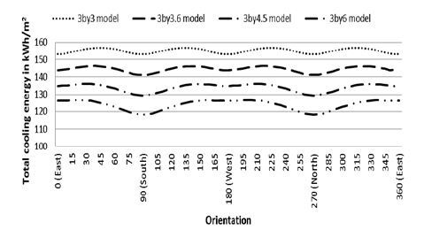
Using the base model and increasing the length of model by ratios 1:1.2, 1:1.5 and 1:2, represented by models 3by3, 3by3.6, 3by4.5 and 3by6 respectively, the best orientation for building is analyzed for minimum heating and cooling load.
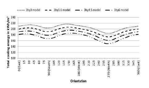
<Fig. 5> shows the cooling energy for windowless models. For the cubic model, there is no difference when the model is oriented to cardinal directions, but as the size of the model increases and the long face of model is oriented to either south or north, the cooling energy decreases. But in case when the orientation is decided by using window on the longer side of the building, large change in energy demand can be observed as shown by <Fig. 6>. Both instances show that when the building is oriented towards N-S, the energy requirement is lower.
<Fig. 6> shows that for models with windows, there is not so much change in cooling energy and is lowest when the window is facing North, which may be because in this position heat is lost through the window instead of heat gain.
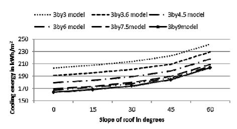
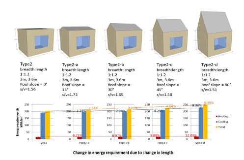
As the Nepal building code [21] allows for a building ratio of 1:3, two more models are added to study effect of building size on energy requirement, represented by 3by7.5 model (1:2.5) and 3by9 model (1:3). <Fig. 7> shows that when the volume of the model increases, by increasing the length, cooling energy decreases. There is 6% decrease in cooling energy for each successive increase in length whereas a change in volume by increase in the slope of the roof tends to increase cooling energy by 3%.
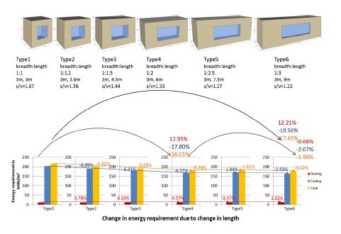
<Fig. 8> shows change in energy requirement when the aspect ratio of building changes. Upto the ratio of 2, the heating energy increases and the cooling energy decreases, decreasing the total energy requirement. From 1:2 to 1:2.5, heating energy decreases by 3.5% and cooling energy and total energy requirement increases by only 1.94 and 1.51% respectively. But again when the ratio increases to 1:3, the heating energy increases and both cooling and total energy decreases.
<Fig. 9> shows the increase in energy requirement when the roof slope increases by 15˚ successively. Instead of using all the models from Fig. 6, only the model Type 2 (aspect ratio of 1: 1.2) as representative model. At first the increase is very small, but as the slope increases, energy requirement increases at a higher rate. Upto 30˚ (Type2-b), the increase is quite low, only about 2% increase in cooling energy but at 60˚ (Type2-d), this change is very high.
3.2. Thermal mass design
The Living Standard Survey of Nepal has identified basically three types of construction for outer wall, which are mud bonded bricks/stones, cement bonded bricks/stones and wood and tree branches[7]. In case of roofing materials, 30% of the household live in buildings with tile or slate roof, 28% live in galvanized corrugated tin sheet house and 20% live in concrete roof houses [7]. As stone is not a common building material in Biratnagar, it has not been considered for this study.
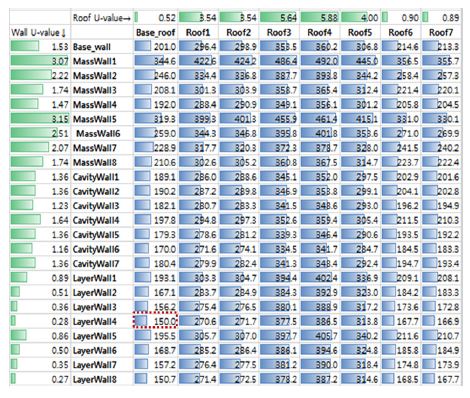
<Table 1> and <Table 2> show the thermal property (U-values) and tentative cost per square meter in nepali currency which is Rupee (NPR) for different building materials combination.
<Fig. 10> shows that the lowest energy requirement might not come from the combination of envelopes with lowest U-values. In <Fig. 10> The U-values in W/m2K are shown in the first row for the roof combinations and for the walls are shown in the first column. The names in the second row and column corresponds to Table 1 and 2 respectively. The numbers with blue bars represents the cooling energy requirement in kWh/m2. For the lowest cooling energy requirement of 149.962 kWh/m2 (25.4% decrease), the best combination is wall made of 120mm mudbrick and 100 polyurethane insulation, LayerWall4, (82% decrease in U-value) and roof made of thatch and CGI, Base_Roof. And comparing cost of LayerWall4 to cost of base case wall, increase in cost is only 2.24%.
3.3. Window design
Windows affect both solar gain and natural ventilation. The glazing type and area affects the amount of solar radiation entering the space and the shading devices helps to control this. Windows being transparent are the only means through which solar radiation can enter into the building and can hence provide solar heating in the building. Thus, windows can cause the cooling energy to increase if there is uncontrolled solar gain from large windows. Shading devices are thus very important to control solar gain through transparent apertures on the building envelope.
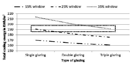
<Fig. 6> also shows the effect of window orientation on energy requirement. Compared to <Fig. 5>, when there is window, the energy requirement varies significantly. To decrease cooling energy, a northern window is better. <Fig. 11> shows the change in energy requirement as the size of window increases along with type of window glazing. A triple glazed window requires the same amount of cooling energy as a window with double glazed window when the size of window is 57% smaller.
3.4. Shading
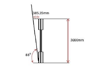
Shading is a very effective way for decreasing solar heat gain both from the windows and wall. Shading devices are designed to obstruct solar gain in summer and let winter sun enter into the space. It can also function as a dual device to direct prevailing winds into the space. The summer solar altitude angle is at an average 83° in Biratnagar. Since the models used for the study here is only 3m, using simple geometry, it can be seen that an overhang of about 385.35 mm can provide summer shade for total wall as shown by <Fig. 12>.
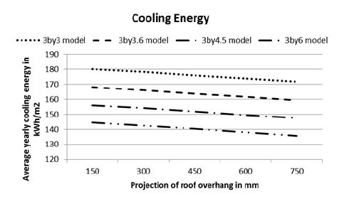
It can be seen from <Fig. 13> that as the width of the shade increases, the cooling energy decreases, meaning as the width of the shade increases, not only the peak summer sun but more solar gain is blocked over the course of the year. This decreases the solar gain for longer periods and decreases the cooling energy requirement.
This also means that the roof overhang cannot be determined by the maximum solar altitude which occurs during Jun 19-Jul 5 which is 83°, as the solar altitude can range from 40-83° during summer periods. Using simple geometry shows that a 750mm overhang can shade for solar altitudes upto 76°, also 600mm overhang can shade for solar altitude angle of 79° and 450mm for 82°. A 300 mm horizontal shade will be able to shade solar altitude of 85° only.
3.5. Natural ventilation
The second direct cooling technique studied here is natural ventilation. It is where natural air breezes can be used for cooling the space in summer.
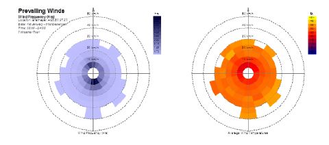
<Fig. 14 (a)> shows the annual wind direction and speed for Biratnagar. We can see that southerly wind is prevalent, so window position can be kept on the south so that it is easy for sun control as well. Upto 40 km/hr wind prevalent in Biratnagar is mostly concentrated on the south direction but <Fig 14 (b)> shows that the temperature of air coming from this direction is about 25°C. Cooler wind of 15°C is concentrated to mostly west and north-west direction. But since the summer outside temperature rises upto 35°C, the air temperature on the south will still be able to cool the environment as it is lower than the ambient temperature.
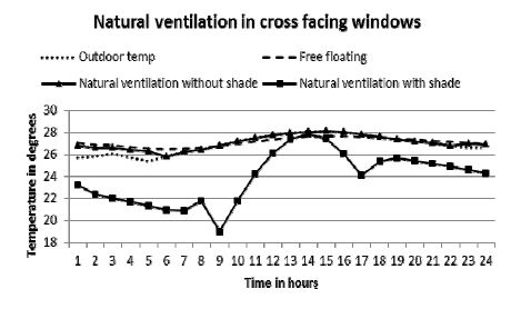
<Fig. 15> shows the inside temperature due to natural ventilation. Compared to an unshaded window, a shaded window performs much better. For an unshaded window, opening the window simply means bringing the air at outside temperature to inside, which simply manages to bring the inside temperature near to outside temperature. So, for natural ventilation to work, a shade or means to cool down the outside air before entering into the space, is imperative.
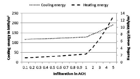
Unwanted ventilation is called infiltration and due to the construction methodology in Nepal, it is very high, which was seen during the calibration of the project model. The infiltration rate calculated for calibrated model is 5 ACH.
Although small increments in infiltration has little effect, like from 0.1 to 0.2 ACH, large change in infiltration can have a significant impact as can be seen from <Fig. 16>. It can also have an impact on the natural ventilation which is mainly achieved by opening the window, that is to say by controlling when the air can move in and out of the spaces.
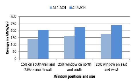
As ventilation works better with opposite facing windows, <Fig. 17> shows the cooling energy requirement for different window positions at 1 and 5 ACH. Since the building orientation is N-S, it is also better to have windows on the North and South walls as well. <Fig. 17> shows that the lowest heating energy occurs when window is on North and South position.
4. Conclusion
Different building design strategies have different effect on the heating and cooling energy requirements. As shown by heating degree days, the heating energy requirement in Biratnagar is very low as compared to the cooling energy requirement. The cooling energy requirement is sixteen times more than the heating energy requirement in the base case model. The increase in cooling energy due to worst orientation as compared to best orientation is an average of 20% over different model size. The maximum change in cooling energy requirement due to change in length of the building is 19% and due to slope is 20%. For building materials, as compared to best case scenario, the worst case scenario can increase the cooling energy by 228% when the cost of construction for worst case scenario is still 46% more expensive than best case scenario. The window can cause 12% change in cooling energy by changing its size. Cooling energy decreases about 1.3% on average due to presence of shading. Improvement in construction technology to provide a more air-tight building envelope can decrease the cooling energy by 10%. So, it can be seen from this study that the thermal conductivity (U-value) of the building envelope has more significant effect on the cooling energy than other design strategies.
As such, energy consumption has not become a big concern in Nepal but the present scenario of increasing construction activity with change in life style and decreasing energy sources calls for more energy conscious designs. By incorporating these design concerns in building design, Nepal can get a head start on decreasing energy consumption in buildings.
References
- Kitio, V., (2014), Resource Efficient Built Environment: methodologies and Lesson learned. Talk program titled “Green Building Design”, Kathmandu Nepal, http://unhabitat.org.np/?post_type=publications&p=1202, accessed 18 Dec, 2014.
-
Pacheco, R., Ordonez, J., and Martinez, G., (2012), Energy efficient design of building: A review, Renewable and Sustainable Energy Reviews, 16, p3559-5373.
[https://doi.org/10.1016/j.rser.2012.03.045]

- Tuohy, P., McElroy, L., and Johnstone, C., (2005), Thermal Mass, Insulation and Ventilation in Sustainable Housing – An Investigation Across Climate and Occupancy, Proceedings of the 9th International IBPSA Conference on Building Simulation, Montreal, Canada.
- Vincent, A., and John, G.R., (2004), Effects of Rationalization of Active and Passive Techniques in the Building Industry. Plea2004 – The 21st Conference on Passive and Low Energy Architecture, Eindhoven, The Netherlands, p19-22.
-
Kumar, A., Suman, B.M., (2013), Experimental evaluation of insulation materials for walls and roofs and their impact on indoor thermal comfort under composite climate, Building and Environment, p635-643.
[https://doi.org/10.1016/j.buildenv.2012.09.023]

- Global economy website, http://www.theglobaleconomy.com/rankings/Energy_use_per_capita/, accessed 18 Dec, 2014.
- Nepal living standard survey 2011, Central Bureau of Statistics-Government of Nepal, Kathmandu, Nepal.
- WECS-Nepal, http://wecs-neep.gov.np/article-energy_situation_ nepal, accessed 18 Dec, 2014.
- Toffin, G., edited by , (1991), Man and His House in Himalayas – Ecology of Nepal, Sterling Publishers, New Delhi.
- Bodach, S., Lang, W., and Hamhaber, J., (2014), Climate responsive building design strategies of vernacular architecture in Nepal, Energy and Buildings, (81), p227-242.
-
Upadhyay, A.K., Yoshida, H., and Rijal, H.B., (2006), Climate responsive building design in Kathmandu valley, Journal of Asian Architecture and Building Engineering, (176), p169-176.
[https://doi.org/10.3130/jaabe.5.169]

-
Rijal, H.B., and Yoshida, H., (2002), Comparison of Summer and Winter Thermal Environment in Traditional Vernacular Houses in Several Areas of Nepal, Proceedings of the International Conference in Building Technology, Hong Kong, China, (2), p1359-1366.
[https://doi.org/10.1016/b978-008044100-9/50169-8]

- Rijal, H.B., and Yoshida, H., (2005), Winter Thermal Improvement of a Traditional House in Nepal, Proceedings of the 9th International IBPSA Conference on Building Simulation, Montreal, Canada.
- Rijal, H.B., and Yoshida, H., (2006), Winter Thermal Comfort in a Himalayan Region of Nepal, Proceedings of International Conference on Comfort and Energy Use in Buildings-Getting them Right.
- Rijal, H.B., Yoshida, H., and Umeniya, N., (2002), Investigation the Thermal Comfort in Nepal, edings of International Symposium on Building Research and the Sustainability of the Built Environment in the Tropics, Indonesia, p243-262.
- Rijal, H.B., Yoshida, H., and Umeniya, N., (2005), Passvie Cooling Effects of Traditional Vernacular Houses in the Sub-tropical Region of Nepal, Proceedings of the 22nd Conference on Passive and Low Energy Architecture, Beirut, Lebanon.
- Leem, Y.T., (2012), Experiment and the Performance Improvement of Eco House Provided by Habitat for Humanity Nepal (HfH_Nepal) – Case Study of Terai Plain Region, Nepal, Korea Institute Ecological Architecture and Environment.
- Manandhar, R., and Yoon, J.H., (2013), Thermal Performance Measurement of Adobe based Affordable House in Nepal. Proceedings of Fall conference of Korean Institute of Architectural Sustainable Environment and Building System (KIAEBS), Seoul, Republic of Korea, p237-240.
- Energyplus Engineering Reference, The U.S.DOE.
- JEPlus, website:, http://www.jeplus.org/wiki/doku.php?id=start, accessed Dec 2013.
- DUDBC Nepal, http://dudbc.gov.np/, accessed7Aug,2014.
- Passive Solar Design, accessed 19May, http://passivesolar.sustainablesources.com/.
