The Visual Performance Evaluation of the Work planes with the Automated blind Control in Small Office Spaces
Among the various building envelope elements, the glass area takes up the largest portion in the office building design. However, a large area of glass can cause problems such as excessive solar radiation, thermal comfort, and glare. Thus it is important to install the glass area to an appropriate level, and control solar radiation and inflow of daylight with blind devices. This study aims to improve the visual performance of the work plane through the automatic control of the venetian blinds. A total of eight kinds of control strategies were chosen; Case 1 does not control the blinds, Case 2 with the blind slats fixed at the angle of 0 degree, Case 3 to 6 using the existing blind control programs, and Case 7 and 8 with improved blind control. Case 3 with 90 degrees had the best energy performance, but the average indoor illuminance was 113lux, which is below the standards. Cases 4 and 5 showed higher levels of interior daylight illuminance with the average of 281lux and 403lux respectively. However, the fixed angles may have difficulties controlling excessive direct sunlight coming into the room and may cause glare. Cases 6 and 7 used sun tracking angle control and cut-off angle control, and the average interior illuminance was measured 250lux and 385lux respectively. Case 8 used the cut-off angle control in an hourly manner, satisfying the standard illuminance of 400lux with an average interior illuminance of 561lux. It was evaluated to be the best method to control direct solar radiation and to guarantee proper level of interior illumination.
Keywords:
Venetian blind, Automated control, Daysim, Profile angle, Cut-off angle, Indoor illuminance1. Introduction
1.1 The study background and objective
In office buildings, the glass area is applied wide in the design aspects, among the building envelope factors. However, this causes the problems, such as thermal comfort or glare, with the induction of the excessive sun radiation heat and daylight. Lately there has been the growing interest in the building energy savings and there are increasing number of the studies to reduce the glass area. The glass area reduction has the benefit in the energy reduction aspects but the problem in the view as well. Thus, it is necessary to install the glass area with the appropriate amount, with the sun shading methods such as the interior blinds to control solar radiation or daylight. The purpose of this study is to improve the visual environment and energy performance on the work planes in the office buildings using automated control of interior blinds.
1.2 Study method
The purpose of this study is to improve the visual environment and energy performance on the work planes in the office buildings using automated control of interior blinds, and the methods are as follows:
(1) Reviewing the blind slats and the position of the sun : The selection of the blind slat angles according to the sun's position is important for the automated blind control. The blind slats and the position of the sun are analyzed for this purpose.
(2) Evaluating the interior illuminance of the subject building according to the control strategy:
K University laboratory, a double envelope structure, was selected as the subject building. The control strategies are categorized in the following cases: no blind(Case1), fixed blind with horizontally 0°(Case 2), blind control (Case3~6), and 2 other added control strategies (Case7, 8). The laboratory blind was controlled using the S company program for the interior illuminance assessment. Also, Daysim program was used for the simulation evaluation according to the control strategy.
2. The theory and literature review
2.1 The blind related theory
The profile angle and the cut-off angle, and the sun tracking angle are required to bring the daylight into the room with the use of blinds on hourly basis. The profile angle considers sun altitude angle, sun azimuth angle, and surface azimuth angle and integrated together into one sun incidence angle on the plane. The formula (1) shows their relationship:
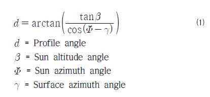
The surface orientation sets the southward 0°standard, with the east (-), and the west (+). The subject building for this study is selected for the east (-30°).

A)Profile angle, B)Cut-off angle, C)Suntracking angle
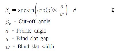
The cut off angle, shown in the formula (2), blocks the direct solar radiation intake. However, it allows the direct solar radiation to be reflected on slats and be redirected to reach the work plane.
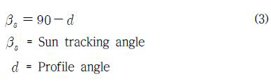
The sun tracking angle6), like the cut off angle, devised to block the direct solar radiation, differs in that it blocks all the direct solar radiation reflected by the slats from reaching the work plane. The sun tracking angle formula is shown in formula (3).
2.2 literature review
Anca D. Galasiu3)studied the automated blind control which compared the two lighting systems, the continuous dimming control and the intermittent control. In the analysis results, 5~45% lighting energy was reduced with dimming control and 5-80% lighting energy was reduced with intermittent control. And Christoph F. Reinhart4) proposed to control the blind(the angle of slat with 0°, 45°, 75°) when the direct solar radiation of the work plane is lager than 50W/m2. But there are not many studies of blind control with measured data in domestic.
2.3 evaluation standard
The visual environment performance evaluation followed the work plane illuminance standard G in the illuminance standard KS A 3011. According to this standard, the standard for the office buildings are 300lux(min.), 400lux (average), 600lux(max.). This study used the average illuminance 400lux as the standard.
3. The visual environment performance evaluation in the automated blind application
3.1 The subject building summary and the simulation condition
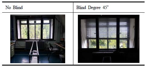
The subject building is summarized in Table1. K University laboratory on 4th floor, with southeast exposure and double envelope structure. The laboratory space is sized as 3.5m(W)☓6.8m(D), with the interior illuminance measuring point to be 2.3m from the exterior window (1m from interior window), installed at 0.75m above the floor, shown the two cases in Fig2: without the blind installed and with one at 45° of slat angle.

Experiment Laboratory

Overview of The Experiment Laboratory
Blind position condition
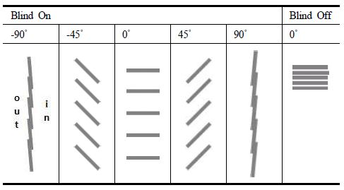
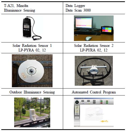
The blind slat angles and their on / off position are shown in Table3. With the horizontal 0° as the standard, when the angle value is in plus, the angle declines toward the exterior. In simulation the application angle range is –90° ~90°; but the real laboratory application blind angle is 0°~90°. The measuring tools are shown in Table4: the amount of solar radiation and the illuminance on the horizontal plane are taken on the exterior roof; the interior illuminance and the exterior illuminance are measured in the laboratory and process the results with the data logger. The blind is controlled with the automated control program. The material property of the subject building is shown in Table5: double envelope exterior glass transmittance is 70%, and the interior glass transmittance 77%.
Blind Slat Angle & On/Off
Measurement Equipment
Properties of Envelope
3.2 Evaluation of the interior illuminance with control strategy
The measurement dates and the application control modes are shown in Table6: the blind control is not applied in the laboratory (Case1~2); the blind control is applied (Case3~6).
Blind Control Strategy
Case 1 is without the blind, Case 2 is fixed with 0° slat angle(horizontally). Case 3~5 are fixed the blind 100% in the energy saving mode, with the change of the angle 90°, 45°, 0°. Case 6 is set on the energy saving mode with the sun- tracking mode added three times a day to control the sun tracking angle. The control sequence for the energy saving mode and the sun-tracking mode are shown in Fig3.

Control Sequence of Energy Saving mode (1), (2)
First, the energy saving mode is calculated on the exterior vertical illuminance.
When the exterior vertical illuminance is 25klux for more than 3 minutes, the blind comes down 100% and gets fixed slat angle. And when the exterior vertical illuminance is below 15klux for more than 15 minutes, the blind is raised by 0%. The sun-tracking mode is not set based on the energy saving mode with the blind coming down to get fixed, but in the mode to set the sun tracking angle in three stages according to the hourly sun angle. All data are measured on the clear sky that the exterior vertical illuminances are larger than 60,000 lux. And the time of the day is set 9am to 6pm.
When the blind is not activated (Case1) is shown in Fig4:

Case1) Outdoor illuminance and Indoor illuminance
the interior average illuminance is evaluated 1,288lux. In the morning, the interior illuminance went up to max. 18,420lux, with the problems predicted, such as glare and cooling load, due to the strong direct solar radiation.
Fig5 shows the case with the office setting with the blind 100% down and fixed 0°slat angle(horizontally).

Case2) Outdoor illuminance and Indoor illuminance
With the interior illuminance measuring point to be 2.3m from the exterior window (1m from interior window), between 9am to 6pm, the interior average illuminance is measured 882lux. Between 9am to 1pm, the interior average illuminance is measured 1,712lux, higher than the standard illuminance 400lux, along with the direct solar radiation, causes glare problem. Between 1pm to 6pm, the interior average illuminance is 215lux below the standard illuminance.
Fig6 shows Case 3, when the energy saving mode is activated with the exterior illuminance of 25klux for more than 3 minutes, the blind comes down 100% and gets fixed slat angle.

Case3) Outdoor illuminance and Indoor illuminance
The interior average illuminance between 9am and 6pm with the 90° control is 113lux, which is below the standard illuminance 400lux. From 2:21pm, the exterior vertical illuminance is kept below 15klux for more than 15 minutes, when the blind is raised (0%) and the interior illuminance goes up to 221lux.
Fig7 shows Case4, controlled similar to Case3, with the blind 100% down set up 45°fixed .

Case4) Outdoor illuminance and Indoor illuminance
The interior average illuminance between 9am and 6pm with the 45° control is 281lux, which is below the standard illuminance 400lux. At 3:17pm the blind is raised (0%) and the interior illuminance goes up to 264lux.
Fig8 shows Case5, with the blind 100% down set up 0° fixed .

Case5) Outdoor illuminance and Indoor illuminance
The interior average illuminance between 9am and 6pm with the 0°control is 403lux, which is similar to the standard illuminance 400lux. At 3:11pm the blind is raised (0%) and the interior illuminance goes up to 307lux.
Case3 shows 90°shield, best in the energy performance aspect but the interior daylight illuminance is deficient. Case 4 and 5 bring in the daylight illuminance more to the interior; in Case 5, the illuminance is closest to the standard illuminance 400lux. However, If the angles are fixed to control, the sun altitude is lower in the winter and the morning solar radiation comes in the excessive amount to cause glare problem. Thus, it is necessary to keep the standard illuminance, blocking the direct solar radiation.
Fig9 shows Case6, based on the energy saving mode, tracked the sun on hourly basis, controlling with the sun tracking angle of September.

Case6) Outdoor illuminance and Indoor illuminance
In the figure at 8:19am the exterior illuminance is kept beyond 25klux for more than 3 minutes, with the blind down 100% and the Sun tracking angle is controlled at 54°. At 11:15 it changes to 29° and the interior illuminance is raised from 263lux to 533lux instantly. At 14:55 the exterior illuminance is kept below 15klux for more than 15 minutes, with the blind up (0%) and the interior illuminance goes up from 198lux to 291lux instantly. The interior average illuminance between 9am and 6pm with Case6 is evaluated 250lux.
4. The control strategies to improve the interior visual environment performance
Case1~6 above show the cases either without the blind control or with the blind control applied but keeping the existing program function, whereas Case7~8 are the control modes to improve these problems, shown in Table7.
Blind Control Strategy
Case7 controls in the energy saving mode, unlike the Case6 that controls with the sun tracking angle, with cut-off angle. The cut-off control allows the reflected portion into the interior through the slats, bringing in more daylight than with the sun tracking angle control. In Case8 the existing program divides one day into 3 parts, applying the Cut-off angle on hourly basis to apply control. Daysim Simulation was used for Case8 to improve the existing control, along with the radiance algorithm, to calculate the daylight coefficient. Daysim Simulation was verified in Fig10, 11, varying the case with the blind: one with and one without.

Daysim & Measured Indoor illuminance - (No Blind)

Daysim & Measured Indoor illuminance - (Blind 100%, 0°)
The evaluation result shows both cases, with or without the blind, had 15.5% error rate and R2 value 0.8583, 0.8898, proving credible.
4.1 Monthly profile angle, cutoff angle, sun tracking angle
Fig12 shows a graph of September and October Profile angle, Cut-off angle, Sun tracking angle. As time passes from September to October, the sun altitude becomes lower and the profile angle is evaluated lower in October than in September. Also, as the profile angle increases, the cut-off angle gets lower. Sun tracking angle is achieved from 90°minus the profile angle. Thus, as time passes the profile angle increases and the sun tracking angle decreases. And the sun altitude is lower in October than in September, the sun tracking angle in October is higher than that in September.

Monthly Profile angle, Cut-off angle, Suntracking Angle
4.2 The Cut-off angle control using the existing control program
Fig13 shows the Cut-off angle calculated in October and the program based on it.

Case7) Cut-off angle(Calculated) & Cut-off angle(Program input)
Cut-off calculated decreases beginning from 7am (47°) toward the afternoon. After 11am, the slat angle value becomes minus value, which is not realistically possible, since the laboratory blind is controlled only 0~90°. Also, when the sun-tracking mode is used, because a day can only be divided into 3 parts, and therefore between 7am and 11am when the cut-off angle is plus value, 47°, the angle that blocks the direct solar radiation at 7 am, was set between 7am and 11am. In the afternoon the angle is set at 0°, since the minus angle value is not realized.
Case7 analysis shows the result the same as Fig14, at 8:38am the exterior vertical illuminance is kept beyond 25klux for 3 minutes, with the blind controlled at 47°. While the interior average illuminance is kept at 441lux, which is above the standard illuminance and at 11am the blind angle changes to 0°, when the interior illuminance goes up to 984lux. At 15:08 the exterior vertical illuminance is kept below 15klux for 15 minutes, when the blind goes up (0%) and the interior illuminance goes up from 176lux to 305lux. Between 9am and 6pm the interior average illuminance is 385lux, a bit below the standard illuminance.

Case7) Outdoor illuminance and Indoor illuminance
4.3 Simulation based hourly cutoff angle control
The following is Case8, same as Fig15, controlled with the hourly Cut-off angle utilizing simulation. Case8 controls slat angles with hourly Cut-off angle in October and blocks the glare causing direct solar radiation; the portion reflected by the blind slats come into the interior to maximize the daylight intake. The graph shows the propensity of the cut-off angle decreasing as time passes by. Between 9am and 6pm the interior average illuminance is 561lux, satisfying the standard illuminance 400lux. Thus, the hourly cut-off angle control blocks the direct solar radiation that influences on the load and the glare, which is advantageous in bringing in the interior daylight.

Case8) Outdoor illuminance and Indoor illuminance
Case1~8 are integrated and analyzed in Fig16. Case1~2 with no blind control and Case3~5 with energy saving mode control with fixed angle, all have glare producing potential. Case6 shows the program sun tracking angle controlled, with the interior average illuminance level 250lux. Case7 is calculated cut-off angle controlled with the interior average illuminance 385lux, a bit below the standard illuminance. In Case8 the hourly Cut-off angle control blocks the glare, bringing in the maximum daylight into the interior, with the interior average illuminance reaching 561lux, well above the standard illuminance level.

Interior average illuminance with different control strategies
5. conclusion
This study selected K University laboratory as the subject building, evaluating the visual environment performance on the interior work plane accroding to the blind control strategy, evaluating the points in the problems and improvements of the existing control methods, drawing the optimum control strategy. It can be summarized as follows:
(1) Without the blind control, the interior illuminance was recorded as max. 18,420lux in the morning. The problems of the glare and the cooling load are predicted due to the strong direct solar radiation.
(2) With the slat angle fixed at 90°, the blind positions are controlled by the energy saving mode (CASE3), in which the interior average illuminance is evaluated as 113lux. 90° shield is the best in the energy performance aspect but with the deficient interior daylight illuminance. Case4 and 5, with 281lux, 403lux, bring in more daylight illuminance into the interior; Case5 provides the illuminance closest to the standard illuminance 400lux. However, the angle is fixed to control, which can cause glare problems in the morning time with excessive solar radiation. Thus, it takes the control method of keeping the standard illuminance, while blocking the direct solar radiation.
(3) CASE6 controls the slat angle with the sun tracking angle, controlling the blind position in the energy saving mode with the sun tracking angle at 54° at 8:19, which changes to 29° at 11:15, changing the interior illuminance from 263lux to 533lux. From 14:55 the exterior illuminance is kept below 15klux for more than 15 minutes, raising the blind (0%) and the interior illuminance goes up from 198lux to 291lux. Case6 was evaluated with the interior average illuminance 250lux between 9am and 6pm.
(4) CASE7 controls the slat angle with the cut-off angle, controlling the blind position in the energy saving mode with the sun tracking angle at 47° at 8:38. The interior average illuminance is 441lux, satisfying the standard illuminance, while it is controlled at 47°. At 11am the blind angle changes to 0°, raising the interior illuminance to 984lux. At 15:08 the exterior vertical illuminance is kept below 15klux for more than 15 minutes; when the blind is raised(0%), the interior illuminance goes up from 176lux to 305lux. Case7 was evaluated with the interior average illuminance 385lux between 9am and 6pm.
(5) Case8 controls the slat angle with the hourly cut-off angle, with the interior average illuminance 561lux between 9am and 6pm, satisfying the standard illuminance 400lux. Thus, controlling the hourly cut-off angle is advantageous in blocking the direct solar radiation intake the most while helping to solve the cooling load and glare problems.
Acknowledgments
This research was supported by Basic Science Research Program through the National Research Foundation of Korea(NRF) funded by the Ministry of Education, Science and Technology(NRF-2013R1A1A2A10005456)
References
- HY Jung, KS Kim, Control Strategy of a Venetian Blind for the Visual Improvement of Workplane, Architectural Institute of Korea, (2010), 12.
- G Yun, KC Yoon, KS Kim, An Experimental Study on Control Strategy of LED System Using Daylight, Korea Institute of Ecological Architecture and Environment, (2010), 12.
- D Anca, Galasiu, Impact of window blinds on daylight-linked dimming and automatic on/off lighting controls, Solar Energy, (2004).
- F Christoph Reinhart, Lightswitch-2002: a model for manual and automated control of electric lighting and blinds, Solar Energy, (2004).
- Tzempelikos A, Daylight and luminaire control in a perimeter zone using an automated venetian blind, Concordia University, Canada, (2007), 9.
- Somfy, Owners manual : animeo® IB+ operating software, (2006).