Revisiting Prediction Tools for Daylight Adequacy and Its Potential Improvement
ⓒCopyright Korea Institute of Ecological Architecture and Environment
Abstract
This study questioned the efficiency of daylight factor as a daylight adequacy and investigated a method of how to complement its weakness by considering a direct sunlight component under a clear sky condition.
The Snowdon visitor centre café was chosen as a case study building and various techniques such as BRE formula, BRE sky protractor, Pilkington dot diagram and mock-upscale model under the artificial sky simulator were used to analyse and compare daylight factor values. An analysis of direct sunlight component under the clear sky condition was carried out by Climate Consultant 5.5, sun path diagram, and the artificial sky simulator.
The result of daylight factor analysis differed by the adopted techniques and it was also contradictory to the results on a direct sunlight penetration. The result not only showed the limitation of daylight factor as a metric but also suggested an improvement by combining it with direct sunlight analysis. The techniques used in this study had a merit of being applied in the early design stage and thus be beneficial to many design professions in order for early daylight performance analysis.
Keywords:
Daylight factor, Direct sunlight, Clear sky condition, Artificial sky simulator, Climate Consultant1. Introduction
As a lighting design tool, the daylight factor (DF) has several advantages and limitations. According to IES (Illuminating Engineering Society) RP-5-13 (2013), Recommended Practice for Daylighting Buildings [1], it addresses only a single sky condition that is prevalent primarily in its country of origin. It does not consider such daylighting design issues as direct and reflected sunlight, latitude, building orientation, time and date, or climatic conditions. Moreover, it is often concerned that satisfying a daylight factor requirement may result in excess daylight under clear sky conditions. Therefore, IES recommends modern climate-based annual daylight performance metrics such as spatial Daylight Autonomy (sDA) and Annual Sunlight Exposure (ASE) in combination with Typical Meteorological Year (TMY) weather data files specific to a given geographical location [1,2].
However, whether like it or not, Climate-Based Daylight Modeling (CBDM) tools are still largely the preserve of lighting simulation experts/researchers [3], and, for an architect or a client, daylight factor would still be widely perceived as a representative indicator of daylighting quality as it is featured in BREEAM UK New Construction Technical Manual [4]. Therefore, several attempts have been made to overcome the limitations of the climate/orientation insensitive daylight factor method without causing high complexity in the evaluation process, and one example would be LEED v4’s ‘clear sky option’ [5]. Although it is a step-forward approach to understand daylight characteristics in a building, there are still a number of obstacles for the practical use. Mardaljevic critiqued the current clear sky option by describing it as ‘the evaluation of a clear sky distribution without the sun’, which is physically impossible luminous environment [3].
The limitations and concerns aside, this paper investigated the potential use of daylight factor not as a comprehensive daylighting performance analysis tool but as a primitive and intuitive tool, especially for an architect or a lighting designer who would like to evaluate their impacts of design choices on daylighting performance early design stage. Therefore, this study has analyzed daylight factor by several different tools such as BRE formula, BRE sky protractor, Pilkington dot diagram and mock-up scale model under the artificial sky simulator, all of which are easily applied in the early design phase.
The café at the Snowdon visitor centre (also referred as ‘Hafod Eryri’) in Wales was chosen as a case building for this analysis. In order to the complement with the limitations of daylight factor method, this study also conducted an analysis of direct sunlight penetration into the case building under a clear sky condition with the sun. Three different methods were applied in this part of analysis; Climate Consultant, sun path diagram, and mock-up model under the artificial sky simulator. The aim of this study is to assess the suitability of daylight factor as an effective indicator when emerged with the analysis of direct sunlight penetration in early design stage. Then, an investigation of the results differences among the tools is followed for suggesting the appropriate way of interpreting from different daylighting analysis tools.
2. A case study building: Hafod Eryri Cafe in Wales
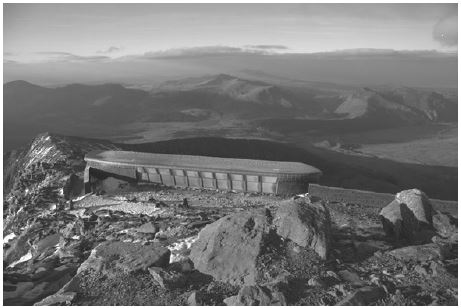
Hafod Eryri is the visitor centre, operated by Snowdon Mountain Railway, at the summit of Snowdon, the highest mountain in Wales, located of 1085m above sea level. The visitor centre first opened in June 2009 and became a popular touristic attraction, which receives on average half a million visitor a year [6]. Figure 1 shows the Hafod Eryri and the summit of Snowdon. The building uses a framed structure and is clad in Portuguese granite. The roof is curved in profile with an angle of 12.5o in relation to the horizontal plane thus the southwest (SW) wall which faces the base of the mountain is 2.5m high while the northeast (NE) wall is 2m higher. This allows an unobstructed view of the summit, as the visitors walk towards it from the café [5]
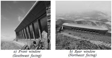
The interior of the café receives daylight by two wall-to-wall windows placed on opposite walls. Both of them are tilled with their external surface facing outside. This feature creates an interesting geometry to the space since in creates the feeling that the viewer can get “deeper” into the view. Also this minimizes the glare from the interior light sources which are not placed on the ceiling, but on the walls. The front window (facing SW, Fig 2 a) covers the entire wall from the ground to the ceiling while the height of the clerestory on the NE wall (rear window, Fig 2 b) is almost 1/3 smaller but placed much higher at 3.5 meters above the ground. The use of shading system on the top of the windows are also noticed from Figure 2.
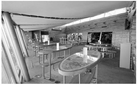
While the exterior granite is used to emphasize the fact that the building is part of the mountainside, the interior of the café is lined with timber to create a warmer ambience, in contrast to the cold and harsh weather conditions outside. Figure 3 shows the interior of the café. Both the internal walls, which are covered with wood and the floor, have low reflectance estimated around 0.2. This creates a warm atmosphere and prevents glare. The ceiling is covered with high reflectance white fabric which follows the angle of the roof and assists the light coming from the bright upper part of the rear window to penetrate deeper into the building.
3. Daylight factor analysis
In order to the analyse daylight adequacy and distribution, daylight factor was calculated by 1) BRE formula, 2) BRE sky protractor, 3) Pilkington dot diagram, and 4) a mock-up model under the artificial sky simulator.
3.1. BRE formula
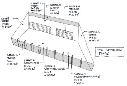
The average daylight factor () of the café was calculated through the BRE formula (Equation 1) [7]. Figure 4 illustrates the hand-sketch of the space volume, materials and reflectance of the floor, wall and ceiling.
| (1) |
where, pr = the mean room reflectance of the room surfaces
Ar = Total room surface area, including glass and window
θ = Angle of visible sky (measured in degrees)
Aw = Area of window
Tw= Window transmittance
Tregenza and Wilson [8] species 0.69 for transmittance of doubling glazing: sealed unit, clear + clear; and 4% reduction due to dirt for a commercial/rural setting. Therefore,
Transmittance of window (Tw) = 0.69 × (1 - 0.04) = 0.66
The total surface area of the room (Ar), including glazing, is 870m2. The average room reflectance (pr) is given from the equation 2.
| (2) |
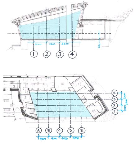
Since there are two windows in the café, which both contribute to the daylight factor and therefore the average daylight factor for the café is the sum of the values calculated to each window. Figure 5 shows the section of the café space indicating angles measured from mid-points of each window. Digitalized technical drawings of the Snowdon visitor centre was not made available for the public access and therefore the drawings in this study were obtained from the scanned magazine article [9].
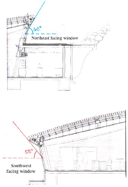
Section of the café indicating angles measured from mid-points of windows (Upper image: southwest facing window, lower image: northeast facing window)
Therefore, the value of the average daylight factor was 3.1 as shown in equation 3, 4 and 5.
| (3) |
| (4) |
| (5) |
3.2. BRE Sky Protractor
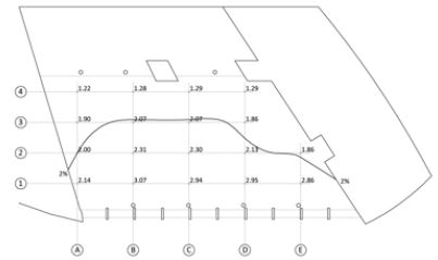
The daylight factor on a reference point can be estimated as a sum of three components, the sky component (SC), the external reflected component (ERC) and the internal reflected component (ICR)) [8]. The ERC and IRC are given by mathematical equations while the SC can be calculated through several methods (e.g. Waldram, pepper dot). Here the BRE sky protractor was used. First, a grid was constructed indicating 18 specific points where the daylight factor was measured which is illustrated in Figure 6. All points were elevated to working plane height.
Table 1 shows the tabulated results from the sky protractor method. The calculation was carried out twice at each point to consider light entering from northeast and southwest facing windows. There were no significant obstructions that can be seen in section, which led to an assumption that no externally reflected component (ERC) had an influence in the daylight for this case.
The sky component (SC) was calculated by multiplying the uncorrected SC by correction factor, which were obtained bya BRE sky protractor. The result indicates that while the northeast facing window has less height than the southwest facing window, it made a significant contribution to daylight distribution in the space due to its location at higher elevation. With relation to the southwest facing window, it was noted that the sky component values dropped by almost 70% from the points at the grid line 1 to the points at the grid line 2.
The average internally reflected component of the daylight factor was calculated from the equation 6:
| (6) |
As there are two windows in the café, the average IRC was needed a separate calculation for each window. The calculation process for the southwest window is shown below (Equation 7):
Tw = 0.66, glazing transmittance
Aw = 40.8m2, area of west-facing window
Ar = 870.9m2, total room surface area
pr = 0.51, average room reflectance
C = 39, coefficient for no obstruction outside the window
Rfw = 0.22, average reflectance of the floor and parts of the walls below mid-height of the window (excluding the window wall)
Rxw = 0.56, average reflectance of the ceiling and parts of the walls above mid-height of the window (excluding the window wall)
| (7) |
The calculation of IRC for the northeast window is as follows (Equation 8):
Tw = 0.66, glazing transmittance
Aw = 16.1m2, area of wet-facing window
Ar = 870.9m2, total room surface area
pr = 0.51, average room reflectance
C = 39, coefficient for no obstruction outside the window
Rfw = 0.45, average reflectance of the floor and parts of the walls below mid-height of the window (excluding the window wall)
Rcw = 0.80, average reflectance of the ceiling and parts of the walls above mid-height of the window (excluding the window wall)
| (8) |
Therefore, the total average value of IRC of the space is as follows:
| (9) |
Based on the results of SC and IRC, daylight factors at 18 specific points were calculated and illustrated in Table2. The same reduction of 0.66 as the one in the average daylight factor calculation was applied for glass transmittance at calculated SC values, which accounts for double glazing and dirt in a commercial/rural setting.
3.3. Pilkington dot diagram
Pilkington dot diagram was used along grid line C to compare the distribution of the SC results through the depth of the space. Again, the SV values needed to be measured separately by the window [8]. Here, the values of SC at the points of grid line C were only measured. Figure 7 illustrates the values of SC at the points of C1 (southwest and northeast).
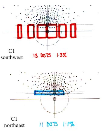
Sky component values for the west and east facing windows at C1 point through Pilkington dot diagram
As shown in Figure 7, the method clearly indicates how the window’s height affects the daylight in the interior space. Diagram ‘C1 southwest’ shows the southwest facing window at their largest angle and yet they still skim the underside of the dot pattern. At point of C3 and C4, zero dots are covered by the southwest facing window. While this method might favor higher windows, this illustrates how low the windows
were and how much sky component was shielded by the roof. Table 3 shows daylight factors along grid line C, by using the Pilkington dot diagram method.
3.4. Mock-up scale model
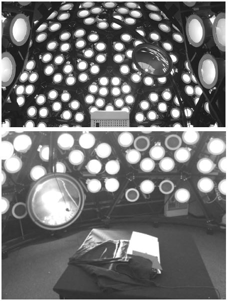
The artificial sky simulator (Fig 8), located at the Bartlett School of Architecture, University College London (UCL), was used to create the artificial overcast sky condition during the evaluation. The simulator consisted of 270 compact fluorescent luminaires for an artificial sky and a 50W MR 16 lamp for an artificial sun. All of the lamps used in the simulator were individually controlled in order to alter the luminance distribution; thereby modelling different sky condition. Here, the overcast sky condition was created. A 1/50 scale model of the café was constructed. Reflectance of the room surfaces were matched by using acrylic paints.
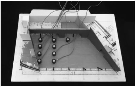
More precisely, a granite colour paper (reflectance of 0.2) was used for the floor, a dark brown colour (reflectance of 0.2) paint was applied for the wall part and the ceiling part was covered by a light colour paint (0.8). Overall, the scale model was closely matched to the real building except that the two windows were left empty in the mock-up model as opening. Daylight factors of 18 points were measured with photocells inside the model (Fig 9).
The daylight factors were estimated by the ratio of illuminance values that were measured both internal and external reference points. Then, 0.66 was multiplied to account for window transmittance and dirt. The result from the physical scale model under the artificial sky simulator is illustrated in Table 4.
3.5. Interpretation of daylight factors
The average daylight factor acquired from BRE formula was 3.1%. Since the decimal place has little meaning on the average daylight factor [10], the value could be rounded off to 3%. Since the value was just above the most of lighting recommendations for non-workspace (e.g. SLL Lighting handbook [11]: 2%, BREEAM technical manual [4]: 2%), it may appear underlit without electric lighting [11]. Logically, this result would a bit surprising considering the fact that the case building is located on the top of highest mountain in Wales with a floor-to-ceiling window on the entire southwest wall as well as no external obstruction. Either the result was due to intention from an architect (e.g. choosing low reflectance materials for interior finishes, which was not the case) or a possible misleading from daylight factor from the overcast sky condition.
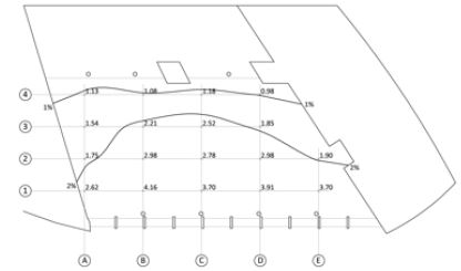
Regarding the daylight factors at a point, the results under sky simulator showed a spread of 2-4% daylight factor in the areas surrounding the southwest facing window (Fig 10). Noticeably, there was no reference point that indicated higher than 5% of daylight factor (the highest value measured was 4.2 at the point ofB1). Based on the result, the café would be recommended to supplement with electric lighting especially at the areas below 2% of daylight factor. Approximately 1% of daylight factors were measured in grid line 4. Overall, the result from the mock-up scale model indicates that the café would be appeared a little dim without the electric lighting, and even the space near the southwest window (floor-to-ceiling window) expected to received low amount of daylight(2.5% to 4% of daylight factor), which correlates well with the above result from the average daylight factor.
Similar result of daylight factor distribution was shown from the BRE sky protractor method in Figure 11. A spread of 2-3% of daylight factor surrounding the southwest facing window. The 2% contour line takes a similar shape between artificial sky simulator and BRE sky protractor. Calculated SC values in Table 4 enabled to interpret the result in more detail. First, SC values from southwest window dropped by approximately 70% from the grid line 1 to grid line 2. This resulted in that from the grid line 2 to 3 northeast window had more impact on daylight than southwest window. In the grid line 4, almost no SC values were measured from both side of windows, and thus daylight in this area was primarily reflected light. The points of D2 and E2, southwest window contributed more on daylight factor and this was due to the non-even building design. The result from Pilkington dot diagram showed the same pattern but it was found that SC values from this tool are more subjective to window height (from the floor level) than other tools.
The results of acquired daylight factors all indicates that the café space appeared to be a slight lack of daylight and if a client or an architect only relied on this information, a design modification might have been suggested in the early design stage to achieve higher DF values. Raising the height of the roof by about a meter, for example, would result in an increase of 3.5% of daylight factors at points, which allows achieving above 5% of daylight factor on most interior area. Then, the numbers may look better in a paper but, daylight factor is known to be a limited indicator mainly due to its assumption on hypothetical overcast sky condition. In order to verify the results from the daylight factor analysis, the impacts of direct sunlight under the clear sky condition were investigated in this study, too.
4. Analysis of sunlight penetration
This section assessed direct sunlight penetration under the clear sky condition into the café interior space by three different methods; 1) Climate Consultant 5.5, and 2) sun path diagram, and 3) mock-up scale model under the artificial sky simulator.
4.1. Climate Consultant
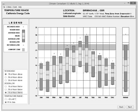
First, the shadow angle caused by the shading system was needed to be decided before the analysis on the sunlight penetration into the cafe. The shadow angles of the southwest facing window were 45° (with the shading system) and 55° (without the shading system). The shading angle of the northwest facing window was 50° the non-shading device in use was 60°. Climate Consultant 5.5, which is a simple to use, graphic-based computer programme that interprets raw weather data file [12], was used. In terms of the weather condition of the Snowdon visitor centre, the input of Birmingham (52.45°N, 1.73°W) weather data file was used instead as it provides the closest data to the case building’s geographical location. As shown in Figure 12,a yearly average temperature in Birmingham was about 10oC and averages at any months were quite below the comfort zone of temperature (20°Cto 24°C). Temperatures higher than 25°C were only observed in July and August throughout a year. Therefore, the amount of direct sunlight exposure in only July and August should be considered whether there would be a case of overheating by direct sunlight exposure.
Figure 13 illustrates a sun shading chart with an overlaid shading calculator of the northeast window from the 21st June to 21st December. According to the visitor center’s web site [6], the café opens at 10:00 am and closes at 18:00 pm and therefore the analysis would focus on the opening hours. As shown in Figure 14, without the shading system in use, direct sunlight penetrated through the northeast facing window from the sunrise till 09:30 am (in June), 09:40 am (in July), and 09:45 am (in August). During the winter (November and December) months, direct sunlight penetrated through northeast facing window from the sunrise until approximately10:30 am. The result suggests that the shading system on the northeast facing window would not be in use throughout a year. The visitor centre received the direct sunlight penetration via the southwest window and the result is shown in Figure 14.
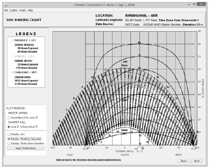
Sun shading chart showing shading calculator overlay (Northeast window) (Grey area indicates the protection of the direct sunlight when the shading system was in use)
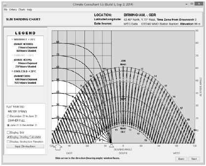
Sun shading chart showing shading calculator overlay (Southwest window) (Grey area indicates the protection of the direct sunlight from the shading system)
During the hottest time of the year (July and August), direct sunlight penetrated from shortly before and after the lunch hours as 13:15 pm (July), and 11:15 am(August) and lasted until the sunset when no shading system was in use. If the shading device applied, there would be almost no direct sunlight penetration in July and also a significant decrease in the amount of direct exposure in August, which starts from 13:15 pm till the sunset. Almost 2 hours of protection (from 11:15 am to 13:15 pm) was expected by the shading system attached in the southwest facing window. There was almost no effect of the shading system in winter. The analysis with the Climate Consultant clearly indicated the effectiveness of the shading device as well as the expected hours of being directly exposed by the sunlight.
4.2. Sun path diagram
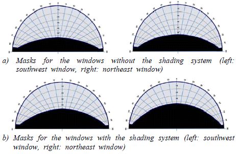
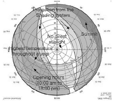
With the sun path diagram method, there was a need to draw the shading mask protractor first. The same angles, defined in Section 4.1, were used and their results on the shading protractor are shown in Figure 15a and Figure 15b. The shading protractors were, then, overlaid on the sun path diagram [13] for latitude N 53.07° and longitude 4.07°, and were adjusted to the orientation of the windows.
Figure 16 shows the final results of the sun path diagram. The result was the basically the same as the one from the Climate Consultant 5.5. In July and August, direct sunlight penetrated into the café through the northeast window from the sunrise till 09:30 am. Again, the shading system was found to be effective to protect approximately an hour of direct sunlight just before the opening time and one hour after the lunch hour in July, and August. During winter, the shading system was not effective as suggested by the Climate Consultant 5.5. Both analysis tools indicate that the direct sunlight penetrated into the space, with or without the shading after 14:30 when the temperature was the highest of a year.
4.3. Mock-up scale model
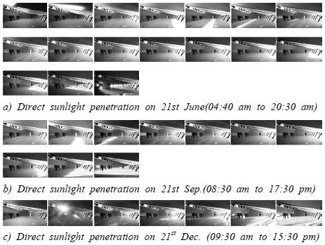
The physical mock-up model (1/50) was used to assess the direct sunlight penetration under clear sky conditions. The artificial sky simulator at UC provided a clear sky condition with the sun for three different times of date, 21st June, 21st September, and 21st December. In order to investigate the sunlight penetration, Digital single-lens reflex camera (DSLR), Cannon EOS 750D, was inserted inside the mock-up model and took snapshots with an interval of an hour. Figure 17 shows the direct sunlight penetration on the mock-up scale model with an interval of an hour.
As shown in Figure 17, the direct sunlight penetrated from through the Northeast window at the sunrise of the day and the penetration creates various different light patterns either on the ceiling or the floor differently by the time of year. The result suggests that this method, compare to the others, was not suitable to assess the exact time of direct sun exposure into the interior space, however, this tool provided visually intuitive results to an architect or a lighting designer for their early design assessment. The result also provided potential areas of discomfort glare from the direct sunlight at different time of a day or a year.
The analysis of the direct sunlight under a clear sky condition by three different methods, indicate that the visitor café was well exposed to the direct sunlight from just after the lunch time (in summer) or before the lunch time (in winter)if we consider only the opening hours. Although accumulated amount of the direct exposure could not be provided by these methods, the results clearly show that the shading system at the southwest window may or not need to be used to reduce the direct exposure by an hour during summer. Such result was quite contradictory to the earlier results from the daylight factor analysis. As discussed in Section 3.5, the average DF and DF at a point indicated that the interior space received slightly insufficient amount of daylight to be considered as a well-daylit space. If an architect or a lighting designer only relied on the daylight factor results, and modified their design accordingly, they might raise the roof by a meter, and then the café would completely be over-exposed to the direct sunlight.
5. Discussion and Conclusion
In this study, several daylighting performance analysis tools were investigated. The café at the Snowdon visitor centre in Wales was chosen as a case building. The study has mainly looked at two different aspects of daylight performance in the interior; daylight adequacy and direct sunlight penetration throughout a year. The indicators of the daylight adequacy were the average daylight factor in a room and daylight factor at a point. The one result from this study is that daylight factors varied, subject to which method were applied. The variations were found up to approximately 30% between mock-up scale model and manual calculations such as BRE sky protractor and Pilkington dot diagram. Although BRE sky protractor and Pilkington dot diagram resulted in very similar values in daylight factors, the details in their calculation, specifically in SC (Sky Component), showed a significant difference. The result from the Pilkington dot diagram seems to be highly influenced by the height of window location. Once a window is located in high elevation, sky components by Pilkington dot diagram showed significantly higher values than the ones from BRE sky protractor while a window is placed on a low elevation level; the reverse result was found (See Table 4 and Table 5 on grid line C). Another finding in this aspect is that the manual calculations were less sensitive approaches to assess the distribution of daylight, especially in a building where low amount of daylight is expected. The case study building had a relatively high IRC (Internal Reflected Component) value due to its bright ceiling reflectance, which heavily influenced on the calculation of daylight factors and resulted in rather uniform spread of daylight factors compare to the values from the mock-up scale model. Based on such finding, this study suggests that careful interpretation is needed to assess daylight factors. More specifically, once the average daylight factor is relatively low (between 2% to 3% or below 2%),considerations on height of window locations and reflectance of interior finishes should be made before interpreting daylight factors in order for preventing from misleading. Therefore, an architect or a lighting designer should be avoided to referring the results from the computer simulation programs without cross-checking especially when the average DF value is relatively low. Also, the limitation of the DF as a metric was found by another aspect of daylight performance analysis.
Three different methods were applied to investigate the direct sunlight exposure under a clear sky condition; Climate Consultant, sun path diagram and mock-upscale model under the artificial sky simulator. The results from the Climate Consultant and sun path diagram show exact duration of direct sunlight penetration. With the weather data assessed by the Climate Consultant, there would almost be no need for shading system throughout a year although long hours of direct sunlight exposure were found due to the extreme outdoor weather condition at the site. The results from this analysis complemented with the limitations of the results of the DFs. The mock-up model under the artificial sky simulator, in the meantime, provided in-detail statement of penetration pattern. The result illustrates the changes in sunlight penetration pattern in three dimensions, which would be particularly helpful for an architect or clients to assess their desired shape of sunlight exposure during a day at any time of a year. However, high demand in the physical resources for this method would be a drawback. According to revisit several tools for daylight adequacy and the direct sunlight penetration in a building interior, all of the tools have potential to be simply applied in the early design stage, and two kinds of daylight analysis tools not only complement the limits of daylight factor as a metric but also provides more in-detail statement of daylighting quality.
References
- IES (Illuminating Engineering Society), (2013), RP-5-13 Recommended practice for daylighting buildings, New York, IES.
- IES (Illuminating Engineering Society), (2012), LM-83-12 Approved method: Spatial daylight autonomy (sDA) and annual sunlight exposure (ASE), New York, IES.
- Mardaljevic, J., (2013), Rethinking daylighting and compliance, Journal of Sustainable Engineering Design, 1(3), p2-9.
- BRE (Building Research Establishment) Group Ltd, (2016), Technical manual SD7076, BREEAM UK New construction non-domestic buildings, Watford, BRE Group Limited, Retrieved on 6th May 2017, from http://www.breeam.com/BREEAMUK2014SchemeDocument/.
- USGBC (U.S. Green Building Council), (2014), LEED v4 for Building Design and Construction, Washington, DC, (Retrieved on 6th May 2017, from http://www.usgbc.org/resources/leed-v4-building-design-and-construction-current-version).
- Hafod Eyri –Snowdon Summit Visitor Centre, (n.d.), Retrieved on 6th May 2017, from https://www.snowdonrailway.co.uk/pages/summit-visitor-centre.
- BRE (Building Research Establishment) Group Ltd, (1986), Digests 309, Estimating Daylight in Buildings, Part 1, Watford.
- BRE (Building Research Establishment) Group Ltd, (1986), Digests 310, Estimating Daylight in Buildings, Part 2, Watford.
- Rattenbury, K., (2009), Extreme building, Architects’ Journal., 230(3), p22-35.
- Tregenza, P., M. Wilson, (2011), Daylighting: Architecture and Lighting Design, London; New York, Routledge.
- Boyce, P., Raynham, P., (2012), The SLL Lighting Handbook, London; SLL (Society of Light and Lighting, UK).
- Climate Consultant, (n.d.), Retrieved on 6th May 2017, from http://www.energy-design-tools.aud.ucla.edu/climate-consultant/.
- Sunpath diagrams, (2011), Retrieved on 6th May 2017, from http://www.jaloxa.eu/resources/daylighting/sunpath.shtml.
