Harvesting Waste Heat from Building HVAC Systems Using a Thermomagnetic Heat Engine
ⓒ Copyright Korea Institute of Ecological Architecture and Environment
Abstract
This paper deals with the generation of mechanical power and its eventual conversion into electricity from the waste heat of building HVAC systems. Especially, the thermal discharge from the condenser unit of air conditioning systems can be readily exploited to provide electricity to light LED lamps and other electric devices depending on the amount of waste heat available.
A heat engine driven by a thermomagnetic rotor, whose design is mainly based on the magneto-caloric effect of gadolinium (Gd), has been developed. Gd is one of the distinct materials whose Curie temperature is nearly room temperature, facilitating the use of low grade waste heat from HVAC systems. A series of tests were carried out to check the feasibility of drawing power from waste heat ranging from 40 to 65℃.
Results show that a maximum power of 29.4 mW can be produced for a temperature differential of 45℃, which complies with the general principles of thermodynamics.
Keywords:
Harvesting wate heat, Thermomagnetic heat engine, Experimental investigation, Magneto-caloric effect, Gadolinium rotor1. Introduction
Different kinds of waste heat are produced around us every moment; heat discharge from simple heat pumps (air conditioners) to large power stations. There are myriad of systems producing waste heat that constantly influencing our eco-systems causing global warming and contaminate water and air around us. Heat discharge from building HVAC units are one of them, which we use every day for space cooling in hot seasons and cooling in cold seasons. Especially, their detrimental effects are becoming more and more pronounced as almost every building is equipped with one or more of them thanks to the general awareness in indoor working (living) environment with improving economic conditions. Moreover, there is a huge output of industrial waste heat, which is considered as a representing index of a country's status in industrialization. This can be easily witnessed as the United States is blamed for producing enormous amount of waste heat from its energy consumption in industry, which amounts for 20 to 50% of global energy use [1].
The path to sustainable energy is a long one. Using low temperature difference engines to generate electricity from low-grade waste heat is one of the uncomplicated areas that can make some good contribution to realize this objective. In our everyday life, from fans to washing machines and other kind of household and commercial appliances, we can easily see the possibility of drawing useful work if suitable means are applied. What looks very simple, however, is not that easily manageable because they are mostly low temperature heat sources. Especially, power generation from these sources may not be feasible, if not possible in most cases. One of the major problems in developing any power from low temperature heat sources was to create enough torque to drive the rotating unit (rotor), which converts mechanical power to electricity by the so-called electromagnetic effect based on Faraday's law. Many attempts have been made to cope with this fundamental technical hurdle by using various types of Stirling engines, which, however, were not successful in delivering sufficient rotational energy to operate the rotor and generate electricity, [2-4]. Especially, Chen [2] proposed a combined thermal-flow analysis of a simple low temperature differential heat engine; the perspective is to utilize low grade waste heat from industries. Shaislamov et al. [3] developed a TENG, which is capable of generating electricity connected to a rotating disk driven by an LTD heat engine. They were able to produce an effective open circuit voltage of 105 V and a short circuit current of about 1.2 μA. However, an important issue related to the published TENG needed to be addressed, which is about the very low short circuit current of the existing TENG due to insufficient torque.
Apart from using Stirling engines, the present study has explored the effectiveness of using a thermomagnetic heat engine uniquely designed for exploiting the magneto-caloric effect of gadolinium; a rare earth metal. The theoretical framework of our thermomagnetic heat engine has been developed by Zviadaze [5], who analyzed the efficiency of an ideal thermomagnetic engine based on Curie temperature.
Harvesting energy from low temperature differential (LTD) heat sources became more efficient than ever as new technologies and materials were developed in the exploitation of low temperature heat for mechanical power generation and its conversion into electricity [6-7].
Stauss [8] estimated the full capacity of a thermomagnetic generator in conjunction with a shunt material of infinite length. He assumed this because for a magnetic flux, if a longer shunt is used, it requires lesser amount of energy (per volume) to be magnetized. Hence, a shunt of infinite length gives the maximum efficiency that a thermomagnetic generator can attain. He has derived the following equation for its maximum efficiency of a thermomagnetic generator by applying the theory of ferromagnetism developed by Weiss.
| (Eqn. 1) |
In the above equation, H stands for the average magnetic field by a permanent (or electro-) magnet whereas N refers to the molecular field constant. Meanwhile, I and NI represent the intensity of magnetization and the molecular field of the ferromagnetic material, respectively.
Elliott [9] used the magnetic characteristics of a permanent magnet to estimate the maximum power that a thermomagnetic generator can generate:
| (Eqn. 2) |
He assumed a sinusoidal manner for the temperature variation of a shunt at a given angular frequency (ω), where V refers to the volume and μr stands for permeability of a permanent magnet.
Gadolinium(Gd) [10] opened a new page in the development of thermomagnetic generators, especially, its application for the exploitation of wasted thermal energy of low temperature. Different types of thermomagnetic generator can be developed by its unique physical property where its Curie temperature is around 20℃(room temperature). Curie temperature here refers to the temperature at which a transition of magnetic property takes place between ferromagnetic and paramagnetic. One can easily harness low temperature waste heat to generate mechanical power if he is able to take advantage of this low Curie temperature. Generally, Heusler alloy performs better than crystalline gadolinium in the operation of thermomagnetic generators. The Curie temperature of 125℃ of the material is, however, much higher than room temperature and this limits its application for utilizing low grade waste heat.
The main objective of this work is to study the performance of a simple thermomagnetic heat engine, where thermal energy from LTD heat sources can be effectively converted into mechanical power, and eventually, electrical energy. The engine has been designed such that it can readily create torque to spin a rotating device (rotor), which is driven by exploiting the magneto-caloric effect of a material called “Gadolinium(Gd).” Gd is a typical substance (chemical element) which demonstrates a magneto-caloric effect such that the intensity of magnetism varies with temperature. Gadolinium exhibits the property of ferromagnetism at 25℃ or lower and paramagnetic properties at temperatures of 25℃ or higher. Taking advantage of this peculiar feature, the basic component of an electro-magnetic generator (Gd rotor) was designed and experimentally tested for its performance in converting heat energy to mechanical power.
2. Design and construction of Gd rotor
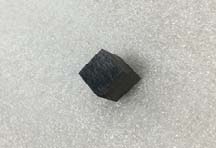
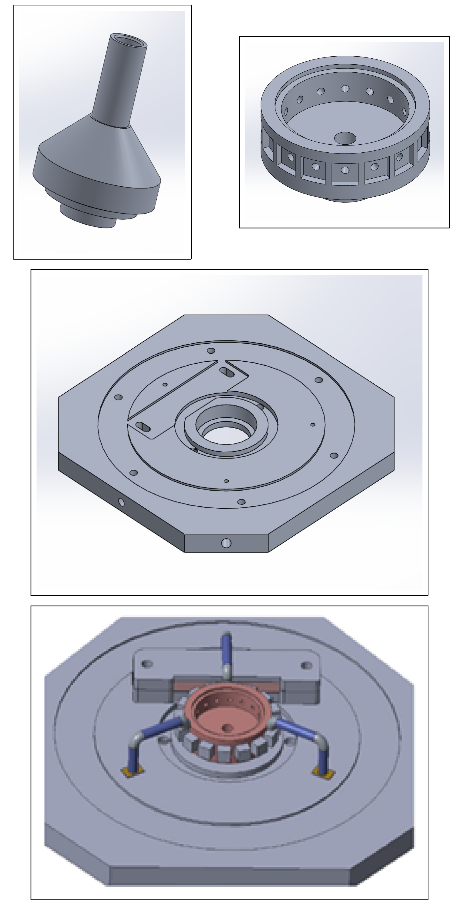
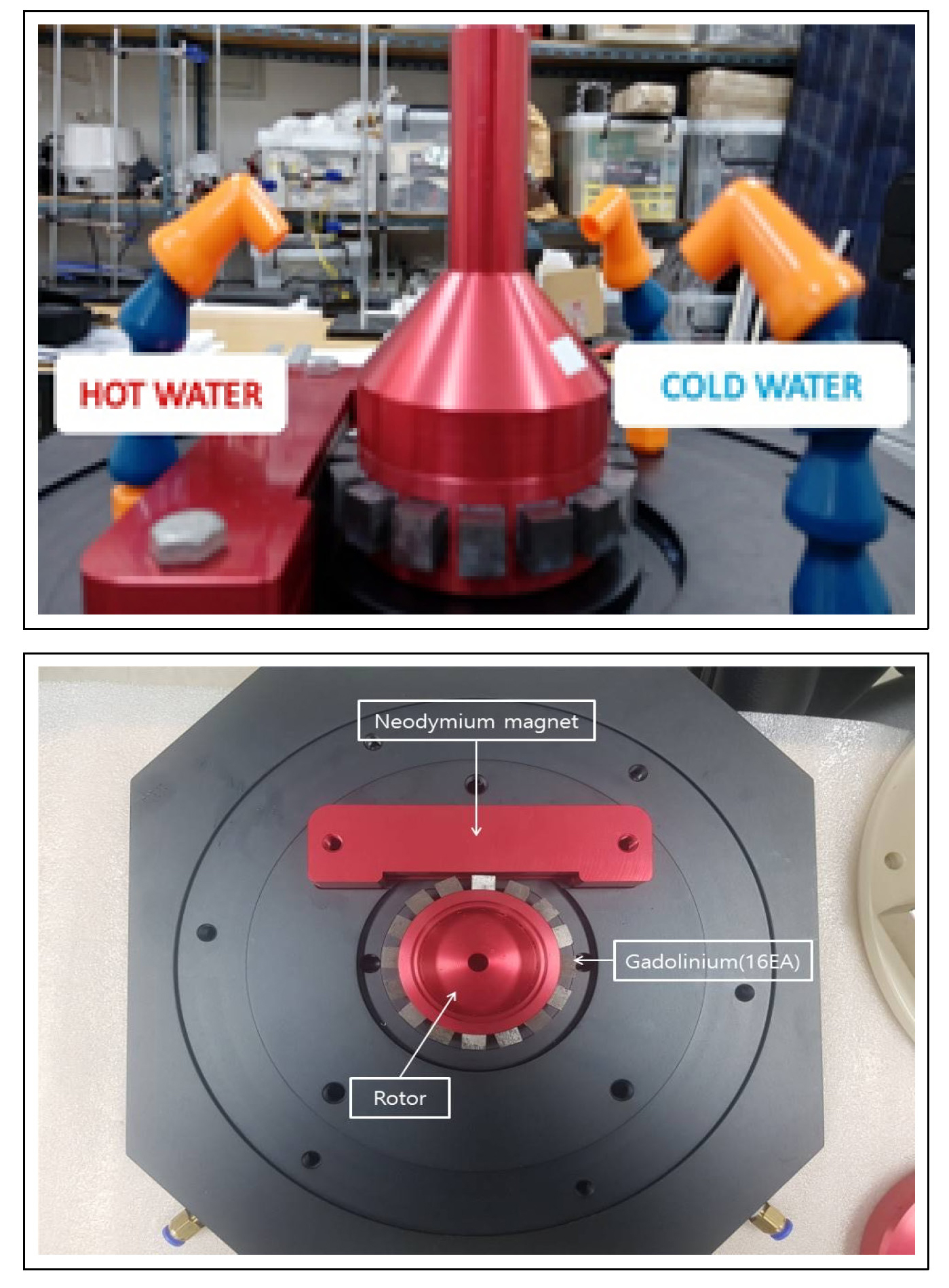
As aforementioned, a simple rotor has been designed and built based on the concept of applying the magneto-caloric effect of Gd, the "Gd rotor", as shown in Fig. 2. The Gd rotor is cylindrically shaped and mainly consists of sixteen Gd blocks and a bar magnet (neodymium bar magnet). The distance between the neodymium magnets and the rotating shaft was set to be less than 1 mm. Each Gd block had the shape of a cube with dimensions of 1 cm × 1 cm × 1 cm in size and was processed from Gd of 99.9% purity. On one side of the rotor, a neodymium bar magnet of 10 cm × 2.5 cm × 1 cm was placed such that the distance between the bar magnet and Gd blocks was maintained within 1mm. The detailed specifications of the rotor is given in Table 1.
Two streams of hot water and a stream of cold water arranged at an interval of 120° were constantly flown over Gd blocks, changing their magnetic property between ferromagnetic and paramagnetic. This change in the magnetic property of Gd blocks interacting with the bar magnet resulted in rotational motion of the rotor and eventually the conversion of thermal energy into mechanical energy (power generation). The maximum torque generated depends on how fast the magnetic property of Gd blocks is changing between ferromagnetic and paramagnetic.
Fig. 1. shows the refined Gd block used in this work, while Fig. 2. shows the schematic design of a Gd rotor.
3. Performance measurements
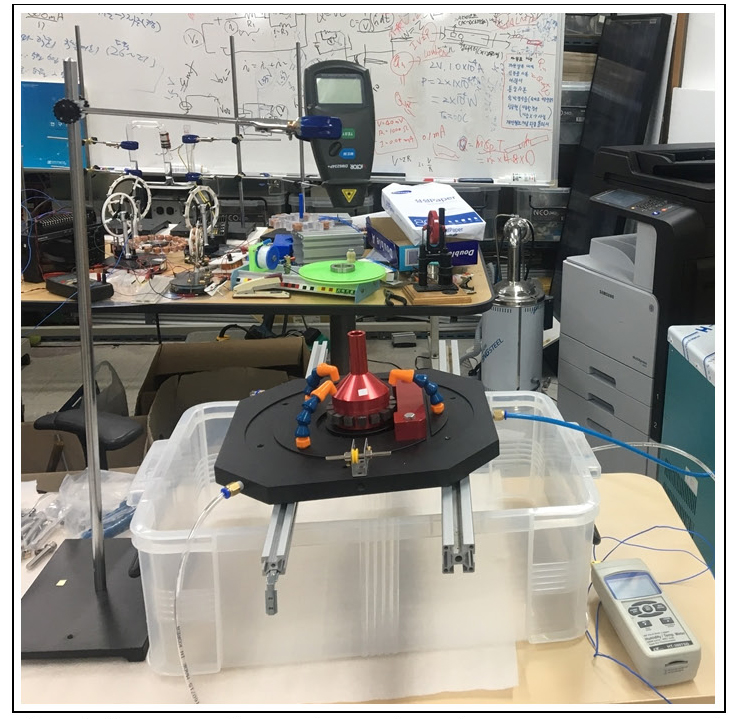
A series of tests were performed to assess the mechanical power developed by the rotor by monitoring its rotational speed(RPM) and measuring the work done (by rising weight) under different operating conditions. As shown in Fig. 3., three water jets set 120° apart were used, where one hot water and two cold water jets provided the heat energy and extract thermal energy from the Gd rotor as it turns. That is, the rotor perfectly realizes the classical thermodynamic principle of the Kelvin-Planck statement as it converts heat energy to mechanical power.
The RPM of the Gd rotor was monitored and its output was calculated using the basic work formula of force x distance. Temperature differences of the applied water jets were 25 ℃, 35 ℃ and 45 ℃ for the operation of the Gd rotor. As for the cold water jet, the water from mains was used, which remained close to 25 ℃. A flow rate of 300 ml/min was maintained for the water jets as they flow through a 3.8 mm diameter tube. Weights were attached to the rotating shaft of the Gd rotor to determine its mechanical output as the temperature of the hot water jet and the mass changed during the operation. The weights used were 5g, 10g, 20g, and 50g.
4. Experimental results
4.1. Mechanical power
Table 2. and Fig. 5. present the variation in the rotational speed (in RPM) of the Gd rotor as it is driven by the water jets impinging on the Gd blocks with changes in load(weight) and temperature differential of the jets applied. As shown, the RPM output increases as the temperature difference between jets becomes larger from 25 to 45 degrees. Eqn. (3) gives the relation between the RPM and the linear speed of the Gd rotor as it spins. The highest RPM of 111.9 was recorded at the temperature differential of 45 degrees and when the applied load was 50g. Meanwhile, the lowest RPM of 74.4 was measured at 25 degrees and 50g, respectively. In general, the larger the temperature difference between jets, the larger the observed RPM was. It could also can be seen that different RPMs can be developed depending on the load even when operated under the same temperature difference between jets.
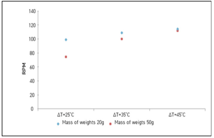
Graphical representation of change in RPMs in response to variations in temperature difference between jets and applied weight(load)
| (Eqn. 3) |
Where
- V=linear speed of rotor(m/s)
- r=radius of rotor(m)
Table 3. and Fig. 6. show the performance of the Gd rotor in terms of mechanical power output under the same operational conditions described above. Eqn (4) gives the simple relation that exists between the mechanical power and the measured values of linear speed and load. Similar to the RPMs, as witnessed above, the output increases as the temperature difference between the water jets grows larger. The highest output of 57.42 mW was observed at the temperature difference of 45°C with an applied load of 50 g. In contrast, the lowest output of 20.34 mW was recorded for the temperature difference of 25 °C and load of 20g. In general, the mechanical power output was proportional to the temperature difference and the applied weight (load).

The effect of applied weight and temperature difference between water jets on mechanical output of Gd rotor
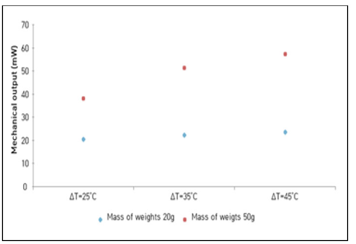
The effect of applied weight and temperature difference between water jets on mechanical output of Gd rotor
| (Eqn. 4) |
Where
- m = mass of weights (kg)
- g = gravitational acceleration (m/s²)
- V = linear speed of rotor (m/s)
4.2. Electric power
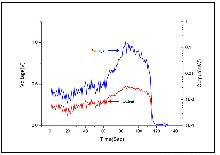
Fig, 7. shows the output of the thermal conversion power generation system when an AC motor was used. When the output at about ΔT = 45°C was measured, the open-circuit voltage reached a value very close to 1.848V. When a resistance of 100 k Ω was applied, the measured voltages ranged from 0.36V to 0.44V. The corresponding outputs for the case were recorded to be from 0.0013 mW to 0.0019mW. Meanwhile, a total output of about 0.00851mW was attained; this was repeatedly checked for the reliability of our experiment.
5. Conclusions
This work explored the performance of a heat engine capable of harnessing low grade thermal energy, especially that discharged from building HVAC systems (55~65℃). The engine readily converts heat into mechanical power thanks to the specially designed rotor, which runs at small temperature differences of as low as 25℃. The rotor is made of 16 gadolinium(Gd) blocks and a permanent bar magnet, whose design has been developed to fully utilize the magneto-caloric effect of gadolinium (Gd). When hit by water jets of different temperatures, attractive and repulsive forces develops between Gd blocks and the bar magnet which results in the spinning motion of the rotor. Experimental results indicate that more power could be developed if larger temperature differences existed between the jets. A maximum power of 57.42 mW was observed at the temperature difference of 45°C between jets with an applied load of 50 g. The maximum measured voltage of 0.44V and total power of 0.00851mW were observed for the case when an AC motor was used. It is, however, interesting to note that the mechanical power output was not just proportional to the temperature difference between jets but also increased with the applied weight (load). By using the thermomagnetic rotor introduced in this work with some modifications as appropriate, various forms of low temperature heat sources could possibly be harnessed without undue difficulties including those related to HVAC systems.
Acknowledgments
This research was supported by the 2017 scientific promotion program funded by Jeju National University
References
- U. S Department of Energy, Waste Heat Recovery: Technology and Opportunities in U.S. Industry, prepared by BCS, Incorporated Mar), (2008.
-
Y. M. Kim, W. G. Chun, K. Chen, Thermal-Flow Analysis of a Simple LTD (Low-Temperature-Differential) Heat Engine, energies, 10(4), (2017), p567.
[https://doi.org/10.3390/en10040567]

-
U. Shaislamov, Y. M. Kim, W. S. Kim, H. J. Jeong, H. J. Lee, W. G. Chun, Hybrid operation of triboelectric nanogenerator for electricity generation by a low‐temperature differential heat engine, Int. J. Energy Re, 41(10), (2017), p1412-1421.
[https://doi.org/10.1002/er.3709]

-
S. J. Jang, Y. P. Lee, K. H. Sim, Experimental Feasibility Study on Low-Temperature Differential Stirling Engines with Water Spray Heat Transfer, Trans, Korean Soc. Mech. Eng. B, 38(6), (2014), p475-482.
[https://doi.org/10.3795/KSME-B.2014.38.6.475]

- A. G. Kvirikadze, М. D. Zviadadze, V. A. Barnov, G. G. Kiknadze, L. A. Zamtaradze, The Efficiency of Ideal Thermomagnetic Engine, arXiv, (2012).
- J. U. Hwang, H. J. Lee, J. I. Kim, S. Y. Lee, J. H. Park, The SMA(Shape Memory Alloy) generator using waste heat, KSMTE ANNUAL AUTUMN CONFERENCE 2016, (2016).
-
M. T. Borset, O. Wilhelmsen, S. Kjelstrup, O. S. Burheim, Burheim, Exploring the potential for waste heat recovery during metal casting with thermoelectric generators: On-site experiments and mathematical modelling, Energy, 118, (2017), p865-875.
[https://doi.org/10.1016/j.energy.2016.10.109]

-
H. Stauss, Efficiency of thermomagnetic generator, Journal of Applied Physics, 30(10), (2004), p1622-1623.
[https://doi.org/10.1063/1.1735020]

-
J. F. Elliott, Thermomagnetic generator, Journal of Applied Physics, 30(11), (1959), p1774-1777.
[https://doi.org/10.1063/1.1735054]

-
H. E. Nigh, S. Legvold, F. H. Spedding, Magnetization and electrical resistivity of gadolinium single crystals, Phys. Rev, 132, (1963), p1092.
[https://doi.org/10.1103/physrev.132.1092]

